Track vacuum pump with optimized bearing arrangement

A vacuum pump and rail technology, which is applied to the parts of the pumping device for elastic fluid, the parts of the rotary piston type/swing piston type pump, the pump, etc., to achieve the effect of long time and less wear

Inactive Publication Date: 2021-08-06
尼得科GPM有限公司
View PDF4 Cites 0 Cited by
  • Summary
  • Abstract
  • Description
  • Claims
  • Application Information

AI Technical Summary

Problems solved by technology

When the pump heats up due to friction in the pump mechanism, the viscous lubricant liquefies, making it easier to overflow the bearings and lose

Method used


Image

  • Track vacuum pump with optimized bearing arrangement
  • Track vacuum pump with optimized bearing arrangement
  • Track vacuum pump with optimized bearing arrangement

Examples


Embodiment Construction

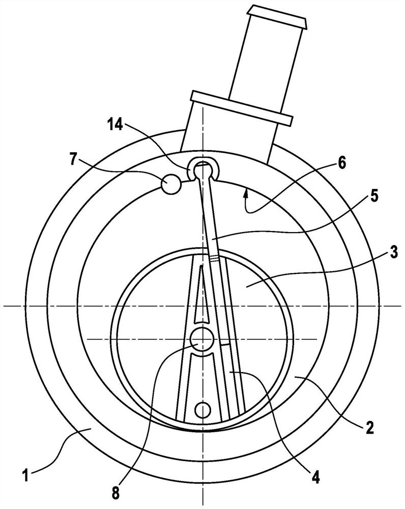
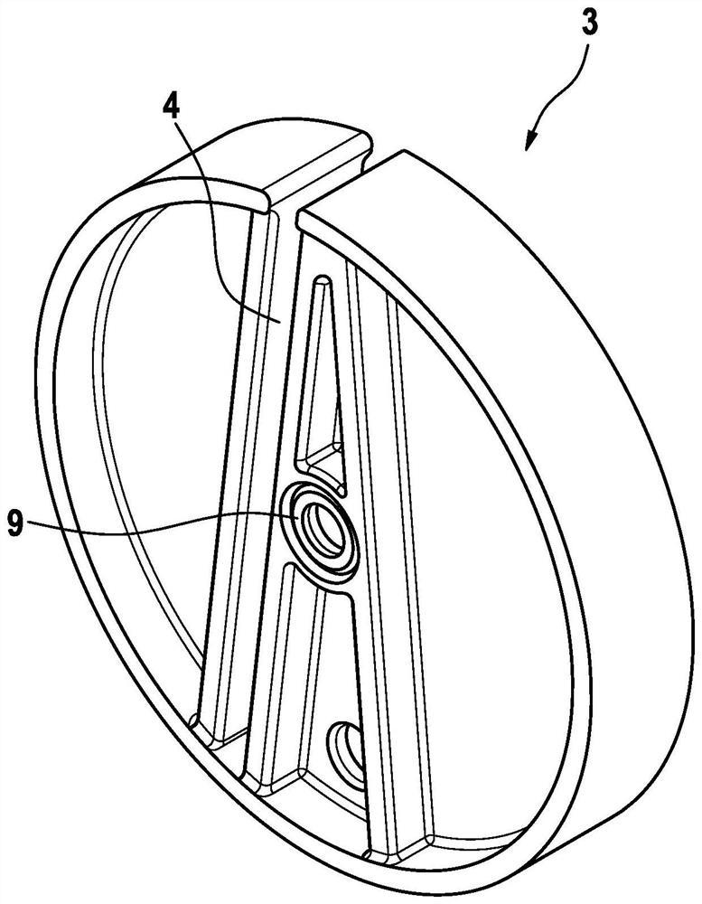
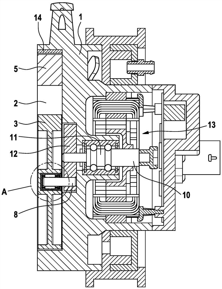
[0036] Such as Figure 1 to Figure 3As shown, an orbital vacuum pump according to one embodiment of the invention is formed by a pump housing 1 comprising a pump chamber 2 with cylindrical chamber walls. In the pump housing 1 , a shaft 10 is arranged to be rotatably mounted by means of a bearing 11 . An eccentric disk 12 with an eccentrically arranged crank pin 8 is fixed on the shaft 10 . The crankpin 8 engages in the center of a cylindrical orbital eccentric piston 3 designed as a piston sleeve.

[0037] The eccentric disc 12 influences the circular movement of the orbital eccentric piston 3 through the pump chamber 2 via the crank pin 8 , wherein the circumferential sliding contact of the orbital eccentric piston 3 with the cylindrical chamber wall is maintained. A guide groove 4 is provided in the track eccentric piston 3 , and the guide groove 4 slidably receives the anti-slip member 5 . The anti-slip member 5 is pivotally mounted at the free end in the pump chamber wa...


PUM


Abstract

The invention relates to a dry running oilless track vacuum pump with friction optimized bearing arrangement. The track vacuum pump comprises a track eccentric piston (3) driven by an eccentric crankpin (8), and a slide stop (5) housed in a guide groove (4) of the track eccentric piston (3), one end of the slide stop (5) being pivotably mounted on the pump housing (1) between an inlet (6) and an outlet (7). A rolling bearing (9) is arranged in a central blind bore (3a, 3b) of the orbital eccentric piston (3), which rolling bearing (9) provides a radial mounting of the crankpin (8) relative to the track eccentric piston (3).

Description

technical field [0001] The invention relates to a dry oil-free vacuum pump with a friction-optimized bearing arrangement. Background technique [0002] Dry-running vacuum pumps are used to evacuate gaseous media, e.g. for creating a vacuum in brake boosters. In the automotive sector, other applications of dry-running vacuum pumps include, for example, the pneumatic adjustment of exhaust gas recirculation valves, the pneumatic adjustment of exhaust flaps, the pneumatic adjustment of guide vanes on turbochargers with variable turbine geometry and Pneumatic adjustment of the bypass of the boost pressure control with the wastegate also includes the actuation of the central locking system, or for opening and closing the headlight flaps. In plant construction, dry-running vacuum pumps are often used to generate negative pressure in electro-pneumatic valves or pneumatic actuators. [0003] Known in the prior art for this purpose are mainly reciprocating positive displacement pump...

Claims


Application Information

Patent Timeline
Patent Type & Authority Applications(China)
IPC IPC(8): F04C18/46F04C18/344F04C25/02F04C29/00F04C27/00
CPCF04C18/46F04C18/3441F04C25/02F04C29/00F04C27/008F04C2240/20F04C2240/50
Inventor 康拉德·尼克尔雅各布·施尼策尔弗朗茨·帕韦莱克
Owner 尼得科GPM有限公司
Why Eureka
Try Eureka