Y-shaped spring locator for hydraulic end of fracturing pump

A locator and fracturing pump technology, applied to pump components, variable displacement pump components, machines/engines, etc., can solve problems such as fatigue crack damage, stress concentration, etc., to reduce stress concentration parts and eliminate the existence of grooves , to ensure the effect of stability

Pending Publication Date: 2019-06-21
宝石机械成都装备制造分公司
View PDF9 Cites 0 Cited by
  • Summary
  • Abstract
  • Description
  • Claims
  • Application Information

AI Technical Summary

Problems solved by technology

[0008] The purpose of the present invention is: in order to solve the stress concentration caused by the groove structure used in the cooperation between the existing spring positioner and the valve box body, resulting in fatigue crack damage and other problems, the present invention provides a hydraulic end of the fracturing pump Y type spring locator

Method used


Image

  • Y-shaped spring locator for hydraulic end of fracturing pump
  • Y-shaped spring locator for hydraulic end of fracturing pump
  • Y-shaped spring locator for hydraulic end of fracturing pump

Examples


Embodiment 1

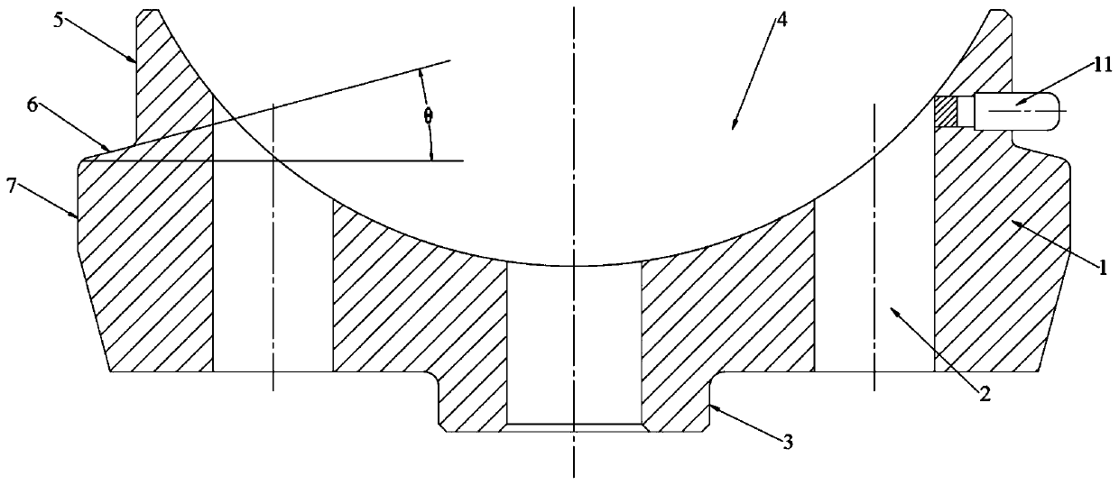
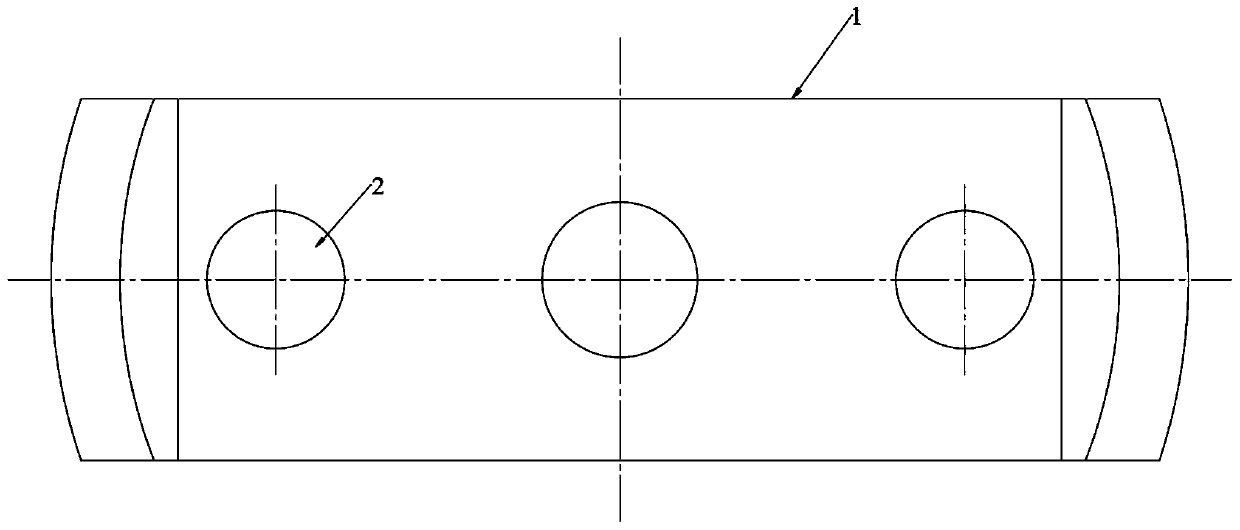
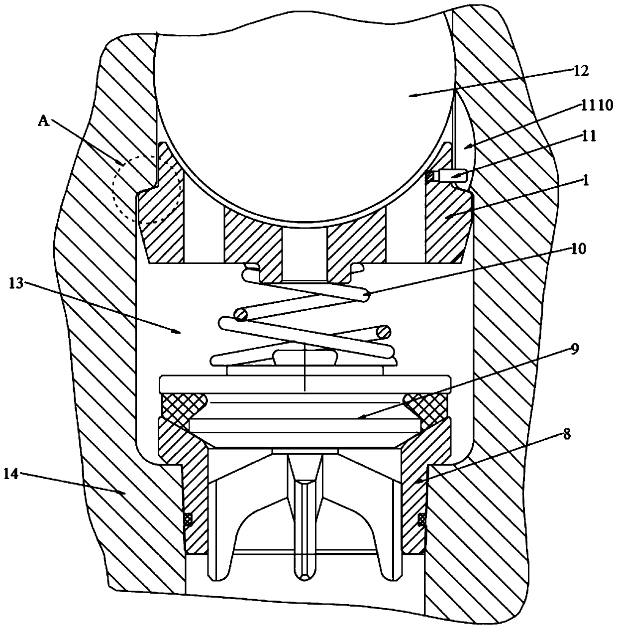
[0032] The Y-shaped spring locator for the hydraulic end of the fracturing pump of the present invention includes a valve box body 14, a suction chamber 13 is opened in the valve box body 14, a suction valve body 9 is arranged at the lower end of the suction chamber 13, and the suction valve body 9 is externally arranged. There is an adsorption valve seat, the upper end of the suction valve body 9 is provided with a suction spring 10, and the upper end of the suction spring 10 is provided with a locator body 1; the lower end of the locator body 1 is provided with a circular boss 3 sleeved in the suction spring 10, positioning The upper end of the device body 1 is recessed downward to form a positioning groove 4 of an arc surface, and the left and right outer walls of the locator body 1 include an upper section 5 and a lower section 7 below the upper section 5, the outer diameter of the upper section 5 is smaller than the outer diameter of the lower section 7, The upper section ...

Embodiment 2

[0035] Present embodiment is further optimized on the basis of embodiment 1 as follows: the taper angle θ of conical surface 6 is 15-75 °, for example: 15 °, 30 °, 40 °, 45 °, 60 °, 70 ° and 75° etc.

[0036] After adopting the above-mentioned technical scheme, the taper angle of the conical surface 6 is 15-75°. According to the matching valve parts of the valve box and the structural characteristics of the valve box body 14 itself, this interval is selected in conjunction with the taper angle to ensure that the positioner body 1 Stability after installation, and the force is evenly distributed on the cone surface 6, less fatigue damage due to stress concentration.

[0037] The material performance requirements for the positioner body have the following requirements:

[0038]

Embodiment 3

[0040] This embodiment is further optimized on the basis of Embodiment 1 as follows: the upper section 5 on one side of the positioner body 1 is provided with an anti-rotation pin 11 along the horizontal direction, and the inner wall of the upper end of the suction chamber 13 is provided with an anti-rotation pin 11. The anti-rotation limiting eccentric groove 1110 is adapted, and the lower end of the anti-rotation limiting eccentric groove 1110 runs through the limiting structure. The width of the anti-rotation limiting eccentric groove 1110 is greater than that of the anti-rotation pin 112-5mm.

[0041] After adopting the above technical solution, an anti-rotation pin 11 is provided on the upper section 5 of one side of the positioner body 1. After installation, the anti-rotation pin 11 enters the anti-rotation limiting eccentric groove 1110, effectively preventing the positioner from rotating in the horizontal direction; The installation process is that the locator body 1 a...


PUM


Abstract

The invention discloses a Y-shaped spring locator for a hydraulic end of a fracturing pump, and belongs to the technical field of fracturing pump devices. The Y-shaped spring locator for the hydraulicend of the fracturing pump is used for solving the problems of fatigue crack damage and the like caused by stress concentration caused by adopting a groove structure in the matching of an existing spring locator and a valve box body. The Y-shaped spring locator for the hydraulic end of the fracturing pump comprises the valve box body, wherein a suction cavity is formed in the valve box body, a suction valve body is arranged at the lower end of the suction cavity, an adsorption valve seat sleeves the suction valve body, a suction spring is arranged at the upper end of the suction valve body, and a locator body is arranged at the upper end of the suction spring; and a circular boss sleeves with the suction spring is arranged at the lower end of the locator body, the upper end of the locatorbody is sunken downwards to form a positioning groove, the outer walls of the left side and the right side of the locator body both comprise upper sections and lower sections, the outer diameter of each upper section is smaller than the outer diameter of each lower section, the upper sections and the lower sections are connected with one another through conical surfaces, limiting structures are symmetrically arranged on the inner wall of the upper end of the suction cavity, and inclined surfaces matched with the conical surfaces are arranged at the lower ends of the limiting structures.

Description

technical field [0001] The invention relates to the technical field of fracturing pump devices, in particular to a Y-shaped spring positioner for the fluid end of a fracturing pump. Background technique [0002] The hydraulic end of the fracturing pump (also called the valve box of the fracturing pump) is the key component of the fracturing pump. The closing movement realizes the cyclic work of sucking and discharging the fracturing fluid, so that the fracturing pump can finally inject the pressure fluid into the downhole in the form of high-pressure hydraulic energy for fracturing operations. Whether the fluid end can work reliably and stably is directly related to whether the suction valve works well. If the suction valve works unstable and has poor durability, it will directly lead to abnormal suction and discharge of the fracturing fluid by the fluid end. This will lead to large fluctuations in flow and pressure, and may even increase the vibration of the fracturing pum...

Claims


Application Information

Patent Timeline
Patent Type & Authority Applications(China)
IPC IPC(8): F04B53/10
Inventor 张甜黎宗琪杨文伟王俊玉朱孟伟唐瑞欢张杰冯一芯代洪川孙和东贾兵兵吴波
Owner 宝石机械成都装备制造分公司
Why Eureka
Try Eureka