Magnetic latch and release apparatus

a magnetic latch and latch technology, applied in the field of magnetic latch and release apparatus, can solve the problems of “stickiness” of the latch, the “stickiness” of the magnetic latch can be problematic, and the person may have very little leverage or room, and achieve the effect of simple latch device, low price, and rapid dissipation of the intensity of the magnetic field

Inactive Publication Date: 2005-03-24
XEROX CORP
View PDF17 Cites 18 Cited by
  • Summary
  • Abstract
  • Description
  • Claims
  • Application Information

AI Technical Summary

Benefits of technology

[0002] Magnetic latches are commonly used to seal doors on cabinets, appliances, and other applications where openings and closings are frequent. A magnetic latch provides an inexpensive, durable, and simple latch device. One disadvantage of magnetic latches is the “stickiness” of the latch when attempting to first budge it from the closed position. The reason is that the magnetic force is greatest when the magnet or its strike plates are in direct contact with the metallic catch plate to which the magnet is attracted. The intensity of the magnetic field dissipates rapidly as the catch plate is moved from the magnet during the process of opening.
[0004] It would be advantageous to combine the inexpensiveness, durability, and simplicity of a magnetic latch with an easier method of freeing the catch plate from the magnet when opening the door. This advantage would be particularly desirable in those instances when a person has little room to reach a handle and must reach under or around encumbrances in order to exert force to open the door. Such a situation exists, for example, if the latch door opens downward within a small space that is lower than the level of an adult's comfortable reach.

Problems solved by technology

One disadvantage of magnetic latches is the “stickiness” of the latch when attempting to first budge it from the closed position.
When a person has only a small space within which to reach and grasp a handle, however, the “stickiness” of a magnetic latch can be problematic.
Worse, when a person must reach under or around an apparatus in order to grasp a handle, the person may have very little leverage or room, and the ‘stickiness” of the magnetic latch may require an awkward yank on the handle rather than a smooth and comfortable pull.

Method used


Image

  • Magnetic latch and release apparatus
  • Magnetic latch and release apparatus
  • Magnetic latch and release apparatus

Examples


Embodiment Construction

[0014] For a general understanding of the present invention, reference is made to the drawings. In the drawings, like reference numerals have been used throughout to designate identical elements.

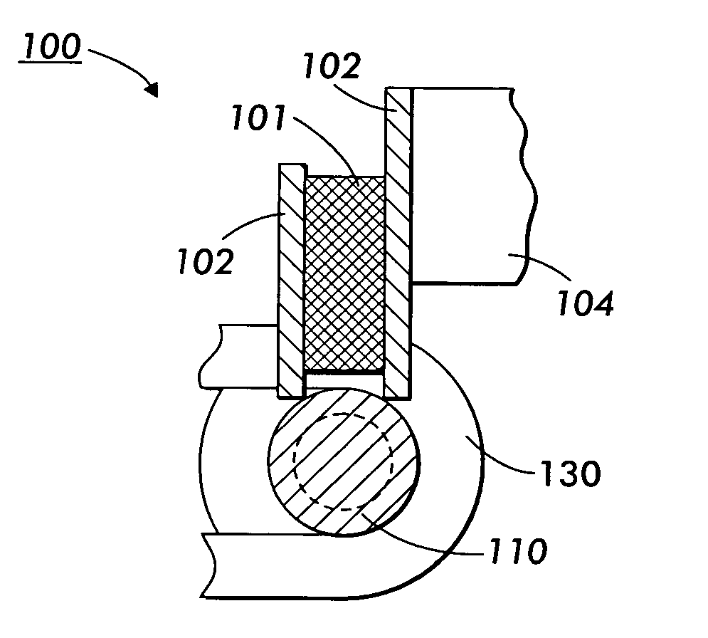
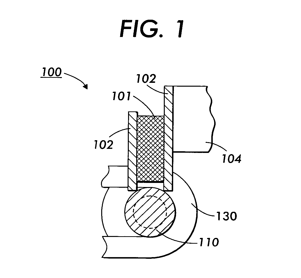
[0015] Referring first to FIG. 1, a schematic cross sectional view is shown of one embodiment 100 of the invention. In this view, magnet 101 is shown with twin strike plates 102. Strike plates 102 can be of any metallic or other material through which a magnetic field can be transmitted. Magnet 101 and strike plates 102 are mounted to an enclosure body by attachment to support member 104. Support member 104 may be part of the enclosure that moves during opening or may be part of the enclosure body, and rod 110 may similarly be positioned opposite support member 104 on either the door or the enclosure body. Support bracket 130 is shown wrapping around rod 110 in order to slidably mount rod 110 in the panel or other member to be latched to member 104.

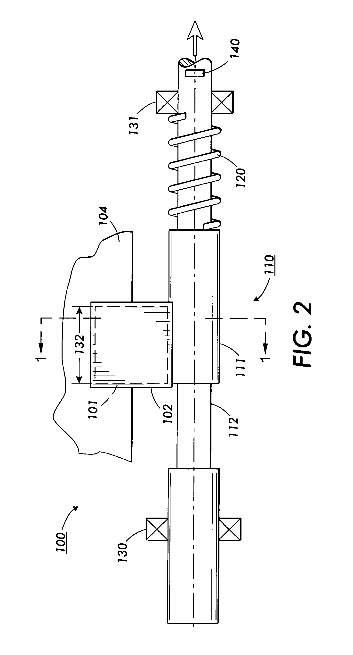
[0016] The magnet and strike plate assemb...


PUM


Abstract

A magnetic latch mechanism and related process for easily and reliably performing a latch operation by moving a magnetically attractive catch plate into and out of engagement with a magnetic field. When in engagement, the latch is secured. When the catch plate is moved away from engagement, the latch can be opened. A magnetic latch for a marking system, particularly for panels covering paper path and jam clearance mechanisms.

Description

FIELD OF INVENTION [0001] The field of the invention is a latch apparatus and more particularly a latch apparatus suitable for securing a movable member such as an enclosure panel with a magnetic latch and, when desired, providing an easy release mechanism from the magnetic latch. BACKGROUND AND SUMMARY [0002] Magnetic latches are commonly used to seal doors on cabinets, appliances, and other applications where openings and closings are frequent. A magnetic latch provides an inexpensive, durable, and simple latch device. One disadvantage of magnetic latches is the “stickiness” of the latch when attempting to first budge it from the closed position. The reason is that the magnetic force is greatest when the magnet or its strike plates are in direct contact with the metallic catch plate to which the magnet is attracted. The intensity of the magnetic field dissipates rapidly as the catch plate is moved from the magnet during the process of opening. [0003] For a typical door, the above ...

Claims


Application Information

Patent Timeline
Patent Type & Authority Applications(United States)
IPC IPC(8): E05C17/56E05C19/16
CPCE05C19/16Y10T292/11Y10T292/42
Inventor LYON, DONALD J.
Owner XEROX CORP
Why Eureka
Try Eureka