Image pickup system, image processor, and camera

a technology of image processing and image capturing system, which is applied in the field of image capturing system, image processing apparatus and camera, can solve the problems of large amount of calculations that must be made by computers, subject to change, and difficult to display the image captured by the camera in constant colors regardless of the kind of incident light, etc., to achieve color constancy or intensity stabilization, perform color correction, and simple calibration

Inactive Publication Date: 2005-06-02
NATURE TECH CO LTD
View PDF6 Cites 84 Cited by
  • Summary
  • Abstract
  • Description
  • Claims
  • Application Information

AI Technical Summary

Benefits of technology

[0058] As has been described so far here above, according to the characteristics of the present invention, it has become possible to provide an image capturing system and a camera therefor capable of correcting a color for achieving the color constancy or intensity stabilization by a simple calibration.
[0059] Further, according to the above characteristics of the present invention, it has become possible to sufficiently perform the correction of the color while keeping the size of the reference image to very small region.

Problems solved by technology

Colors from an object are subject to change by incident light, and it is therefore difficult to display an image captured by a camera in constant colors regardless of the kind of incident light.
Thus, according to the Retinex method, a complex calculation must be performed for every pixel based on the detected light information, posing a problem that a huge amount of calculations must be made by a computer.
Further, if a color of the scene is dominated by a certain color for example, the dominant color is recognized as the color of light source, posing a limit to application.
However, as a practical issue, it is very difficult to insert the white patch directly in the scene that is an object of recording.
Therefore, the highlighted portion must be found independently from a scene already captured, resulting in a very complex procedure of image processing.
Further, since the pixel in the highlighted portion is saturated, it is impossible to identify the color of the light source from them.
Thus, in order for the color correction to be performed accurately, a precise calibration must be performed as a prerequisite for the mapping, and this calibration requires a complex procedure.

Method used


Image

  • Image pickup system, image processor, and camera
  • Image pickup system, image processor, and camera
  • Image pickup system, image processor, and camera

Examples


first embodiment

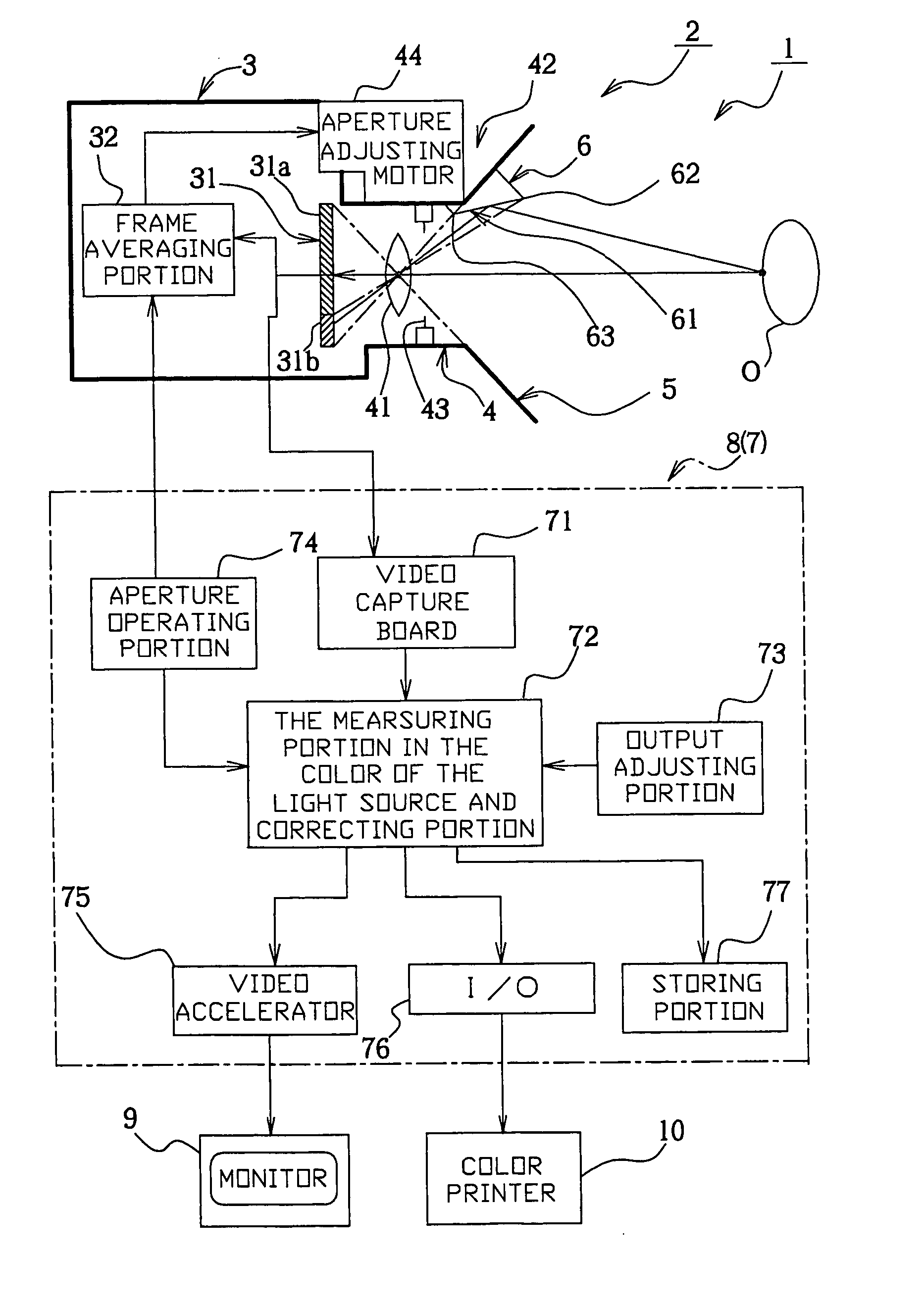
[0101] Next, the present invention will be described with reference to FIGS. 1 through 14. First, alphabetical codes to be used in the description will be defined here below: [0102] XMX: Maximum number of pixels in a horizontal row in an image. [0103] YMX: Maximum number of pixels in a vertical row in the image. [0104] NMIN: Minimum value of a reflection surface boundary. [0105] NMAX: Maximum value of a reflection surface boundary. [0106] S: User-defined image brightness coefficient. [0107] x: Horizontal location of a pixel of the image on a coordinate system. [0108] y: Vertical location of the pixel of the image on the coordinate system. [0109] rd[x] [y],gd[x] [y],bd[x] [y]: Direct image signal values in red, green and blue channels respectively. [0110] rz[x] [y],gz[x] [y],bz[x] [y]: Zero image signal values in the red, green and blue channels respectively. [0111] r[x] [y],g[x] [y],b[x] [y]: Effective input image signal values in the red, green and blue channels respectively (Main ...

second embodiment

[0161]FIG. 15 show a second embodiment, in which the main image sent from the main image capturing portion 31a of the CCD 31 is directly color-corrected by an analog or digital video amplifier 79, and then displayed in a monitor unit 11. The calculation of the constants of proportionality sr sg, sb by the correcting portion 72 is made by using the first and the second reference frames R1, R2 shown in FIG. 14, for correcting the first and the second reference frame groups I2, I3 at a later time. An output adjusting portion 73 is an operating portion for adjustment of an output from the video amplifier 79. This arrangement offers an advantage that the main image is corrected at video-rate processing speed. It should be noted here that the image obtained by a detailed correction based on the main image and the reference image both drawn from the same frame can be recorded by a video recorder 12 via a video accelerator 75.

third embodiment

[0162]FIG. 16 shows a third embodiment, which differs from the other embodiments for example a silver salt film, in that a chemical color film 37 is used as the image capturing device. Specifically, according to the present invention, the color channels of the image capturing device and light detecting element may not be physically separate from each other but may be a substance which forms a plurality of color channels through change in characteristics caused by a chemical reaction. The color film 37 is detachably stored in a film storing portion 36.

[0163] The incident light from the lens 41 is split by a prism 34 to reach the color film 37 and the light detecting element 35. The light detecting element 35 transmits image data to the frame averaging portion 32 for control of the iris 43 and the aperture adjusting motor 44. The present embodiment differs from the other embodiments in that the image processing unit 7, which is a separate unit from the camera 2, has a personal compute...


PUM


Abstract

An image capturing system, image processing system, and camera in which color can be precisely corrected to realize invariability of color through simple calibration while decreasing the area of a reference image part. The system comprises a camera having a lens, an image capturing system device, and a reflecting surface. Reference signal values (rn, gn, bn) are determined by averaging the intensities of the reflected lights of a reference scene received by the image capturing system device from the respective color channels of a plurality of pixel parts. The reference signal values represent the light source color, and a main image is corrected using the reference signal values.

Description

TECHNICAL FIELD [0001] The present invention relates to an image capturing system, an image processing apparatus and a camera therefore including a lens, an image capturing device, a light detecting element and a reflection surface, for correction of an image included in a main scene captured in the image capturing device of the camera, by using information from a reference scene obtained from the reflection surface. BACKGROUND ART [0002] Colors from an object are subject to change by incident light, and it is therefore difficult to display an image captured by a camera in constant colors regardless of the kind of incident light. Human eyes, however, can recognize the colors of the object with constancy even in such an environment, due to an ability known as the color constancy. [0003] Conventionally, two methods of color correction are used in order to achieve the color constancy in the image captured by a camera. One is known as the spatial correction method, in which the correcti...

Claims


Application Information

Patent Timeline
Patent Type & Authority Applications(United States)
IPC IPC(8): H04N5/225H04N9/04H04N9/73
CPCH04N5/2254H04N9/735H04N9/045H04N23/55H04N25/611H04N23/88H04N9/64
Inventor ABDELLATIF, MOHAMED ABOLELLAKITAMURA, KOJI
Owner NATURE TECH CO LTD
Why Eureka
Try Eureka