Obstacle following sensor scheme for a mobile robot

a mobile robot and sensor scheme technology, applied in the field of autonomous robot obstruction detection system, can solve the problems of unsuitability for consumer markets, high cost and power requirements of these types of robotic subsystems, and the available sensor subsystems such as sonar sensors for detecting obstacles on or in the floor or in the order of walls, etc., and achieves the effect of reducing the cost of the system, and improving the accuracy of the system

Inactive Publication Date: 2008-09-30
IROBOT CORP
View PDF295 Cites 192 Cited by
  • Summary
  • Abstract
  • Description
  • Claims
  • Application Information

AI Technical Summary

Benefits of technology

[0007]Accordingly, the control system of the present invention utilizes, in one embodiment, a synchronous detection scheme inputted directly into an A / D port on a microprocessor of the robot. This allows sensor values, and not merely the presence or absence of a wall, to be used to control the robot. The synchronous detection algorithm also allows readings to be taken with and without the sensor emitter powered, which allows the system to take into account ambient light.
[0008]In one aspect, the invention relates to a robot obstacle detection system that is simple in design, low cost, accurate, easy to implement, and easy to calibrate.
[0009]In an embodiment of the above aspect, such a robot detection system prevents an autonomous cleaning robot from driving off a stair or an obstacle that is too high.

Problems solved by technology

Although technology exists for complex robots which can, to some extent, “see” and “feel” their surroundings, the complexity, expense and power requirements associated with these types of robotic subsystems render them unsuitable for the consumer marketplace.
Unfortunately, however, presently available sensor subsystems such as sonar sensors for detecting obstacles on or in the floor or for detecting the wall in order to enter the wall-following mode (or to avoid bumping into the wall) are either too complex or too expensive or both.
Tactile sensors are inefficient to ensure that walls or other obstacles can be effectively followed at a predetermined distance.

Method used


Image

  • Obstacle following sensor scheme for a mobile robot
  • Obstacle following sensor scheme for a mobile robot
  • Obstacle following sensor scheme for a mobile robot

Examples


Embodiment Construction

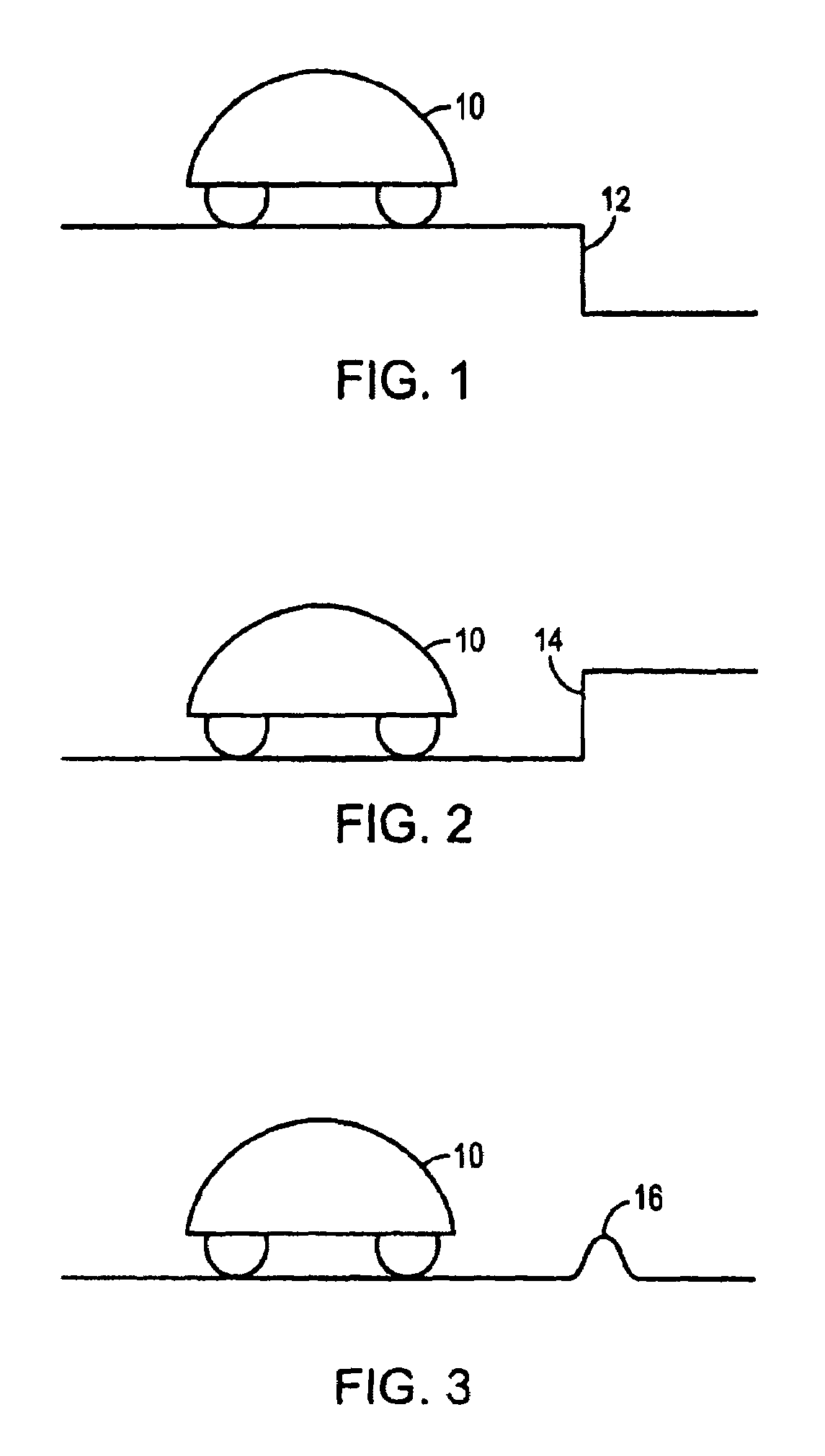
[0072]Robotic cleaning device 10, FIG. 1 can be configured to dust, mop, vacuum, and / or sweep a surface such as a floor. Typically, robot 10 operates in several modes: random coverage, spiral, and a wall-following mode, as discussed in U.S. Pat. No. 6,809,490 and in the Background section above. In any mode, robot 10 may encounter downward stair 12 or another similar “cliff,” upward stair 14, FIG. 2, or another similar rise, and / or obstacle 16, FIG. 3. According to one specification, the robot must be capable of traversing obstacles less then ⅝″ above or below floor level. Therefore, robot 10 must avoid stairs 12 and 14 but traverse obstacle 16 which may be an extension cord, the interface between a rug and hard flooring, or a threshold between rooms.

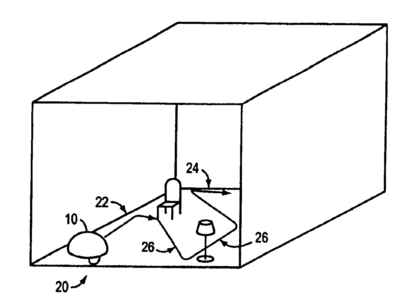
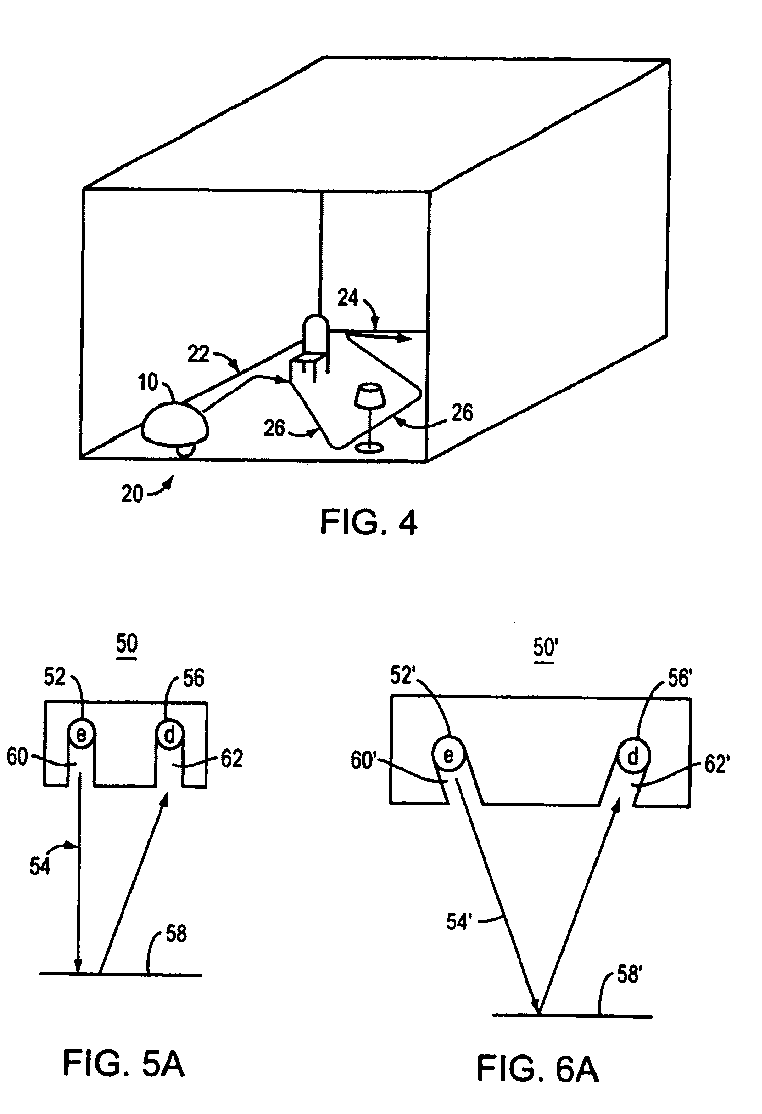
[0073]As delineated in the background of the invention, presently available obstacle sensor subsystems useful in connection with robot 10 are either too complex or too expensive or both. Moreover, robot 10, depicted in FIG. 4, is design...


PUM


Abstract

A robot obstacle detection system including a robot housing which navigates with respect to a surface and a sensor subsystem aimed at the surface for detecting the surface. The sensor subsystem includes an emitter which emits a signal having a field of emission and a photon detector having a field of view which intersects the field of emission at a region. The subsystem detects the presence of an object proximate the mobile robot and determines a value of a signal corresponding to the object. It compares the value to a predetermined value, moves the mobile robot in response to the comparison, and updates the predetermined value upon the occurrence of an event.

Description

CROSS REFERENCE TO RELATED APPLICATIONS[0001]This U.S. patent application is a continuation of, and claims priority under 35 U.S.C. §120 from U.S. patent application Ser. No. 11 / 166,986, filed on Jun. 24, 2005, which is a continuation-in-part of U.S. patent application Ser. No. 10 / 453,202, filed on Jun. 3, 2003 now U.S. Pat. No. 7,155,308, which is a continuation-in-part of U.S. patent application Ser. No. 09 / 768,773, filed on Jan. 24, 2001 now U.S. Pat. No. 6,594,844, which claims priority under 35 U.S.C. § 119(e) to U.S. Provisional Application 60 / 177,703, filed on Jan. 24, 2000. U.S. patent application Ser. No. 11 / 166,986 also claims priority under 35 U.S.C. §119(e) to U.S. Provisional Application 60 / 582,992, filed on Jun. 25, 2004. The disclosures of the prior applications are considered part of (and are hereby incorporated by reference in) the disclosure of this application.FIELD OF THE INVENTION[0002]This invention relates to an obstacle detection system for an autonomous robo...

Claims


Application Information

Patent Timeline
Patent Type & Authority Patents(United States)
IPC IPC(8): G06F19/00G01S15/931G01S17/93G05D1/02
CPCG05D1/0238G05D1/0242B25J9/1697G01S15/931G05D1/024G05D1/0255Y10S901/47G05D2201/0208G05D2201/0215A47L2201/04Y10S901/01G05D2201/0203Y02P90/02G01S17/93
Inventor CASEY, CHRISTOPHERCROSS, MATTHEWOZICK, DANIELJONES, JOSEPH L.
Owner IROBOT CORP
Why Eureka
Try Eureka