
Retractable ball seat having a time delay material

a technology of time delay and material, which is applied in the direction of fluid removal, sealing/packing, and well accessories, etc., can solve the problems of unsatisfactory pressure, further delay, and well experiencing undesirable downtime, and achieve the effect of less well downtim

Active Publication Date: 2008-12-16
BAKER HUGHES INC
View PDF31 Cites 169 Cited by
  • Summary
  • Abstract
  • Description
  • Claims
  • Application Information

AI Technical Summary

Benefits of technology

The patent describes a new type of retractable ball seat for use in oil and gas wells. The seat includes a dissolvable material that acts as a time delay for releasing the ball. This material can be calibrated to determine when it will release the ball. The seat can be customized for different well depths without needing to change the size of the housing. The seat can be selectively closed to allow pressure to actuate a downhole tool. The apparatus includes a housing, a seat, and a plug element that can be dropped down the conduit to block fluid flow through the conduit. The seat can move axially relative to the conduit and the plug element can move axially and prevent the collet from expanding until the dissolvable material is dissolved. The patent also describes an improvement in a retractable ball seat that includes a collet for releasably trapping a plug member. The improvement includes at least one dissolvable material disposed adjacent the collet to prevent the collet from expanding until the dissolvable material is dissolved. The dissolvable material can be a polymer that can be biodegradable. The patent also describes a method for calibrating the dissolvable material to determine when it will release the ball. Overall, the patent provides new methods for controlling the release of the ball in well tools.

Problems solved by technology

However, in some instances sufficient pressure may not be available.
Alternatively, in some wells, pressure, even if available, cannot be utilized because additional intervention steps are required which results in the well experiencing undesirable “downtime” for the additional intervention steps.
Additionally, in some instances, the shear pins fail to shear when they are supposed to, causing further delays.

Method used


Image

  • Retractable ball seat having a time delay material
  • Retractable ball seat having a time delay material
  • Retractable ball seat having a time delay material

Examples


Embodiment Construction

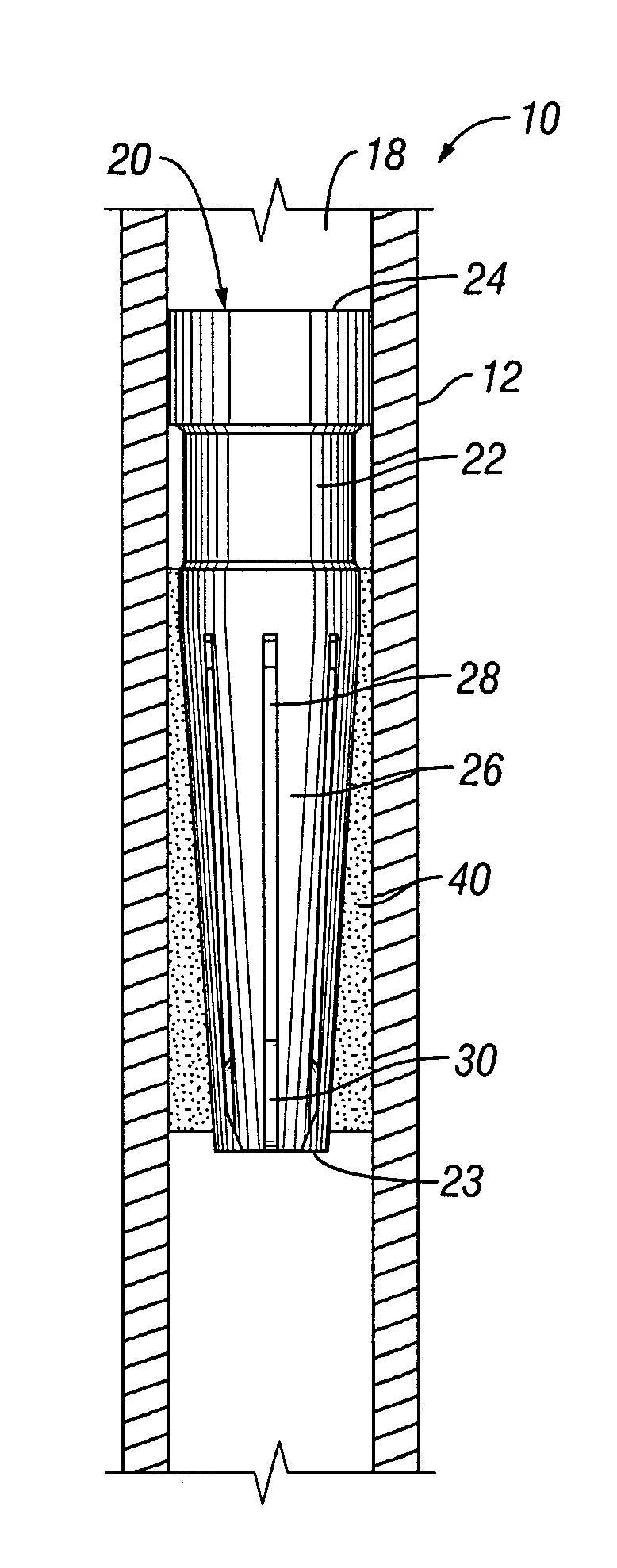
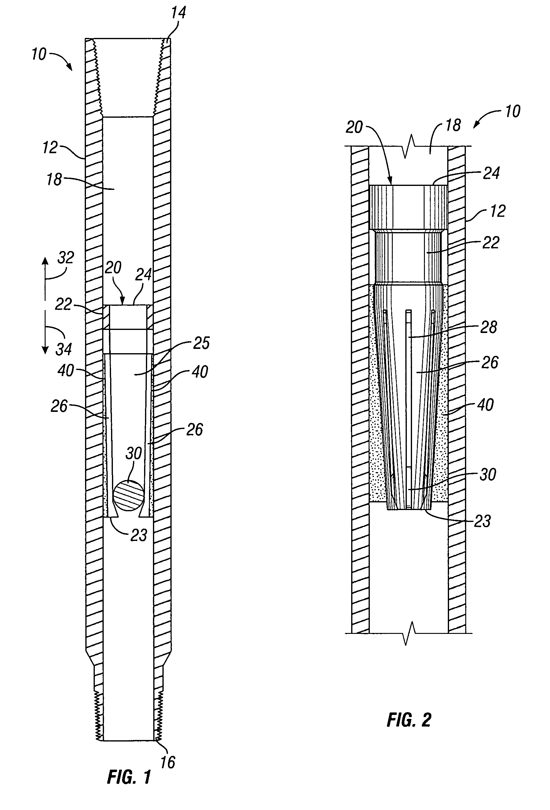
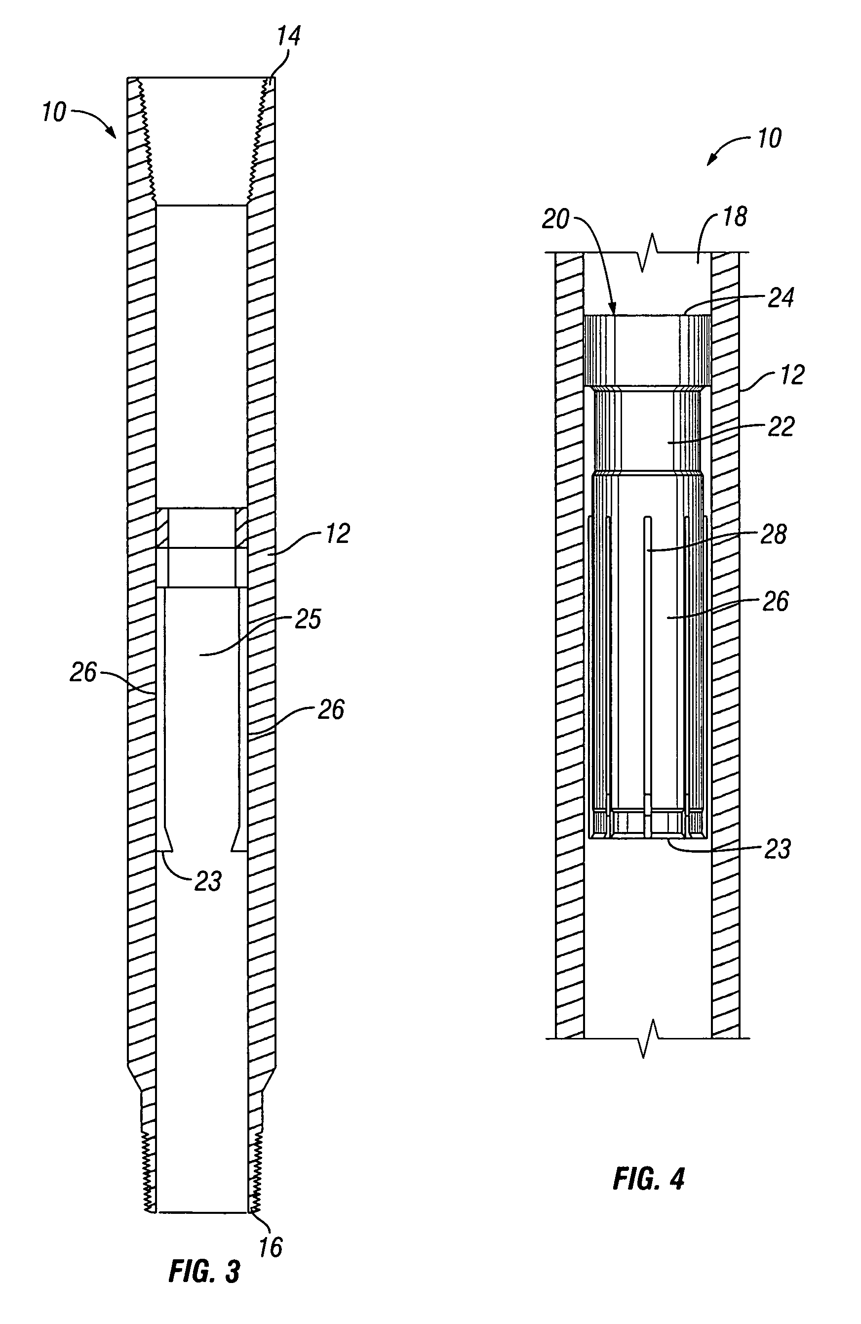
[0026]Referring now to FIGS. 1-4, apparatus or retractable ball seat 10 includes a sub or housing 12 having first end 14, second end 16, and bore 18. Housing 12 is dimensionally shaped to fit within the inner diameter of a wellbore such that the exterior surface of housing 12 is engaged with the inner diameter of the wellbore. Housing 12 has threaded upper and lower end for securing into a string of conduit, such as drill pipe or tubing.

[0027]Seat 20 is disposed within in bore 18. Although not shown, seat 20 is limited against axial movement in bore 18, such as by an internal shoulder. As shown in FIGS. 1-4, seat 20 comprises collet 22 having expandable end 23, open end 24 and passageway 25. Open end 24 of seat 20 is preferably a solid annular member. Collet 22 includes a plurality of collet fingers 26 having slots 28 disposed between each collet finger 26. In the retracted position of retractable ball seat 10 (FIGS. 1 and 2), ball 30 is disposed within passageway 25 and rests on se...


PUM


Abstract

Retractable ball seats having a housing, a seat, and a plug such as a ball are disclosed. The seat has a retracted position that prohibits the ball from passing through the passageway and an expanded position that permits the ball to pass through the passageway. A time delay material, such as a dissolvable material, maintains the seat in the retracted position. The time delay material disintegrates, degrades, or dissolves within a known period of time such that the retractable ball seat can be placed in a desired location in the wellbore and the ball will be released through the passageway within a known period of time.

Description

BACKGROUND[0001]1. Field of Invention[0002]The present invention is directed to retractable ball seats for use in oil and gas wells and, in particular, to retractable ball seats having time delay materials for releasing the ball.[0003]2. Description of Art[0004]Retractable ball seats are generally known in the art. For example, U.S. Pat. No. 3,211,232 discloses a typical retractable ball seat having a collet, a passageway through the collet, and a ball or drop plug. The ball or drop plug is disposed on the seat, preventing fluid from flowing through the passageway. As the fluid pressure above the ball or drop plug builds up, the fluid pressure actuates a tool connected to the retractable ball seat. Thereafter, the collet is moved from its retracted position to its expanded position and the ball or drop plug falls through the passageway. As a result, fluid is no longer being blocked by the retractable ball seat.[0005]Although modifications of retractable ball seats have been made, su...

Claims


Application Information

Patent Timeline
Patent Type & Authority Patents(United States)
IPC IPC(8): E21B29/00
CPCE21B34/14E21B23/0413E21B2200/08E21B23/00E21B33/00E21B34/06
Inventor XU, YANG
Owner BAKER HUGHES INC
Learn More