Lens driving device and electronic camera using the same

a technology of electronic camera and driving device, which is applied in the direction of mountings, instruments, television systems, etc., can solve the problems of large size of the driving device, and achieve the effect of preventing the deterioration of the strength of the barrel holder

Inactive Publication Date: 2007-04-17
FUJIFILM CORP +2
View PDF8 Cites 15 Cited by
  • Summary
  • Abstract
  • Description
  • Claims
  • Application Information

AI Technical Summary

Benefits of technology

[0007]In view of the foregoing, it is a primary object of the present invention to provide a small-sized lens driving device in which an original position of a lens is detected and a lens position is accurately controlled.
[0013]In the lens driving device and the electronic camera according to the present invention, the reflection member is merely disposed inside the barrel holder. Thus, the lens driving device and the electronic camera may be downsized in comparison with a case in that an optical position detector is disposed inside the barrel holder to detect the original position of the lens. Further, since it is sufficient to form the opening in the barrel holder, the strength of the barrel holder is prevented from deteriorating.

Problems solved by technology

However, the lens driving device described in the above-noted Publication No. 60-417 has no space for disposing the optical detector of the PI and so forth.
Consequently, if the original position is detected by using the optical position detector of the PI and so forth, there arises a problem in that the lens driving device becomes a large-size.

Method used


Image

  • Lens driving device and electronic camera using the same
  • Lens driving device and electronic camera using the same
  • Lens driving device and electronic camera using the same

Examples


Embodiment Construction

)

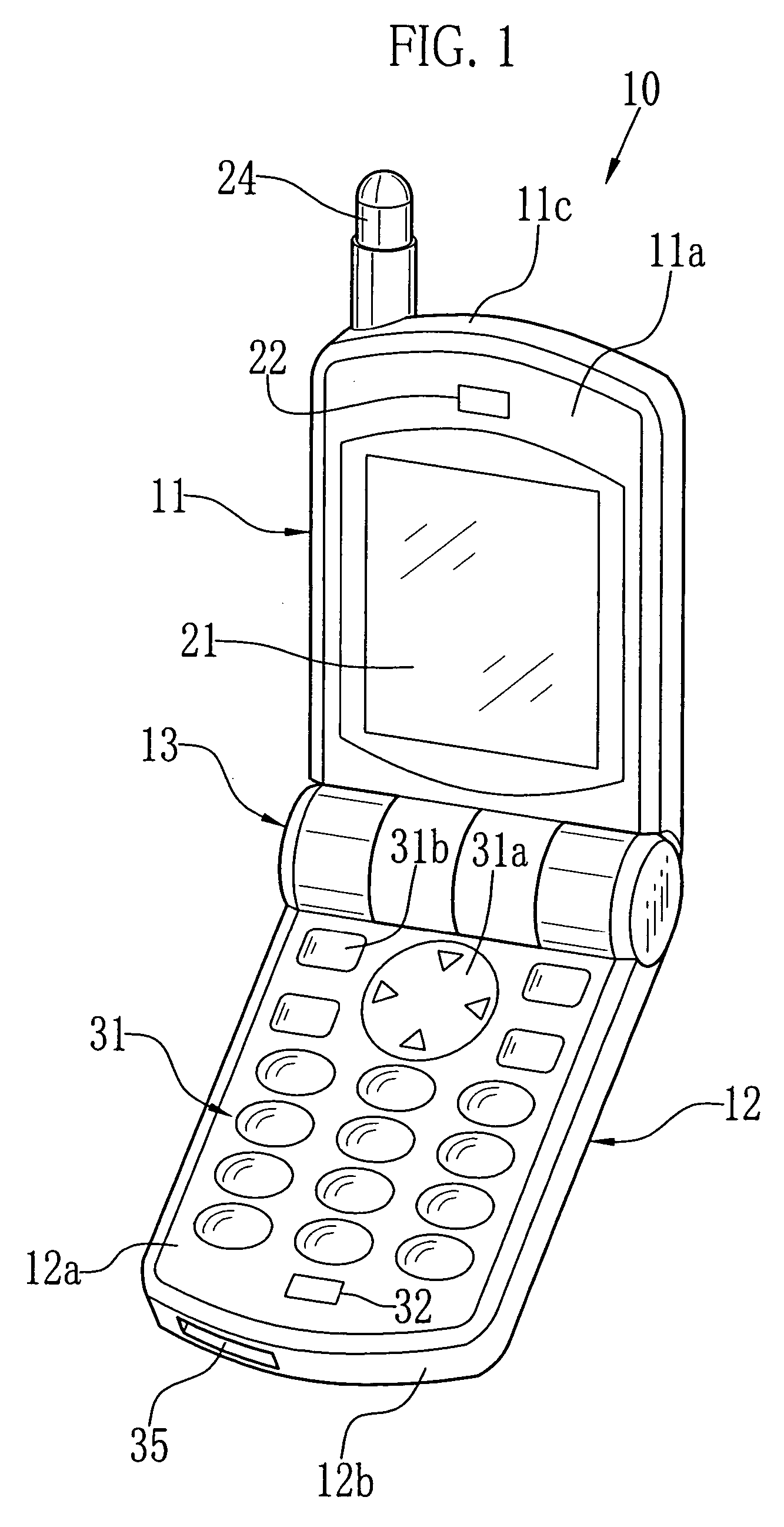
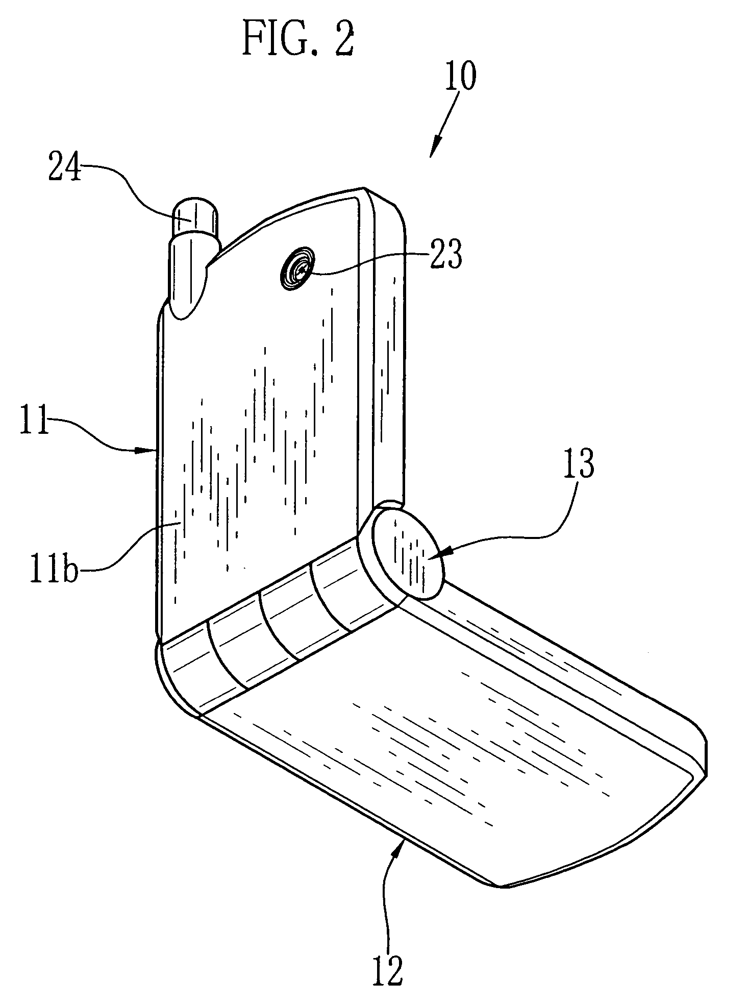
[0025]In this embodiment, a lens driving device according to the present invention is applied to a camera-equipped cell-phone. FIG. 1 is a perspective view showing a front side of the camera-equipped cell-phone 10, and FIG. 2 is a perspective view showing a rear side thereof. The camera-equipped cell-phone 10 comprises an upper body 11, a lower body 12 and a hinge 13 rotatably connecting these bodies 11 and 12.

[0026]The respective bodies 11 and 12 have a rectangular thin shape. The upper body 11 and the lower body 12 are rotated around the hinge 13 between an open position and a closed position. The open position is shown in FIGS. 1 and 2. In the closed position, the upper body 11 and the lower body 12 are folded so as to be parallel to each other.

[0027]The front 11a of the upper body 11 is provided with an LCD panel 21 and a speaker 22. A taking lens 23 is exposed at the rear 11b of the upper body 11. Moreover, the top 11c of the upper body 11 is provided with an antenna 24. The L...


PUM


Abstract

A circumferential surface of a lens holder is provided with a reflection member having different reflectance relative to a surrounding portion thereof. An opening is formed in an upper cover at a position confronting the reflection member at a time when the lens holder is kept in an original position being as a close-end position. The upper cover is provided with an optical position detector disposed so as to be adjacent to the opening. The optical position detector optically detects the reflection member via the opening when the lens holder is kept in the original position. Consequently, an original position of a taking lens held by the lens holder is detected.

Description

BACKGROUND OF THE INVENTION[0001]1. Field of the Invention[0002]The present invention relates to a lens driving device for detecting an original position of a lens and for controlling a lens position, and further relates to an electronic camera using the lens driving device.[0003]2. Description of the Related Art[0004]In recent years, electronic cameras are widely used. This kind of the electronic camera is downsized and lightened for the purpose of improving portability. Moreover, it is general to install the electronic camera in a small-sized equipment of a cell-phone, a PDA (Personal Digital Assistant) and so forth. In such a case, it is required to further downsize and lighten the electronic camera. Thus, it is also desired to downsize a lens driving device to be employed in the electronic camera.[0005]In order to solve the above problems, a lens driving device utilizing a hollow stepping motor is considered (see Japanese Patent Laid-Open Publication No. 60-417, for instance). T...

Claims


Application Information

Patent Timeline
Patent Type & Authority Patents(United States)
IPC IPC(8): G02B7/02G02B15/14
CPCG02B7/08H04N5/2254
Inventor OTAKA, HIROYUKISASAKI, RYOTA
Owner FUJIFILM CORP
Why Eureka
Try Eureka