Automobile wheel

A technology for wheels and automobiles, applied in the direction of wheels, web-type wheels, rims, etc., can solve the problems of increased wheel vibration, achieve the effect of suppressing vibration and improving operation safety

Inactive Publication Date: 2012-05-30
CENTRAL MOTOR WHEEL CO LTD
View PDF6 Cites 0 Cited by
  • Summary
  • Abstract
  • Description
  • Claims
  • Application Information

AI Technical Summary

Problems solved by technology

When the automobile wheel rotates, the peripheral part of the valve is elastically deformed outward due to the centrifugal force generated by the self-weight of the attached air pressure detection device, and the vibration of the automobile wheel tends to increase.

Method used


Image

  • Automobile wheel
  • Automobile wheel
  • Automobile wheel

Examples


Embodiment 1

[0037] figure 1 is a longitudinal sectional view showing the automobile wheel 1 of the first embodiment, figure 2 It is a side view. In this automobile wheel 1, the spoke flange portion 25 of the spoke 3 is embedded in the well portion 13 of the rim 2, and the corner weld of the well portion 13 and the spoke flange portion 25 is integrated into a so-called well fitting. Combined structure. Furthermore, the rim 2 and the spokes 3 are formed by forming a steel flat plate, respectively, and the automobile wheel 1 of the first embodiment is a steel wheel with a two-piece structure.

[0038] In addition, in this embodiment, the direction from the back side of the spoke 3 to the design surface side is the front side, and the opposite direction is the back side. In addition, the direction along the wheel radial direction perpendicular to the central axis L of the automobile wheel 1 toward the central axis L is referred to as the inward direction, and the opposite direction is re...

Embodiment 2

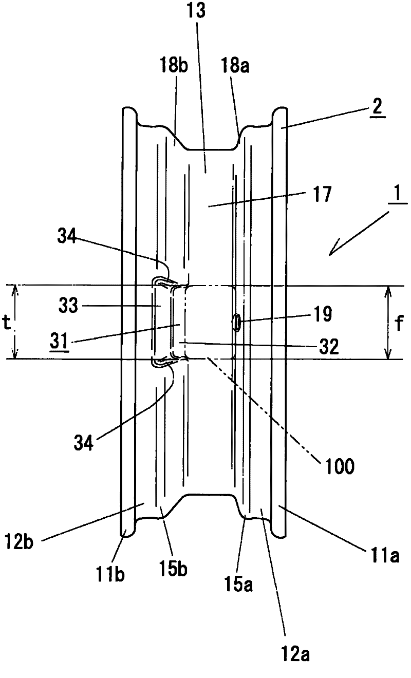
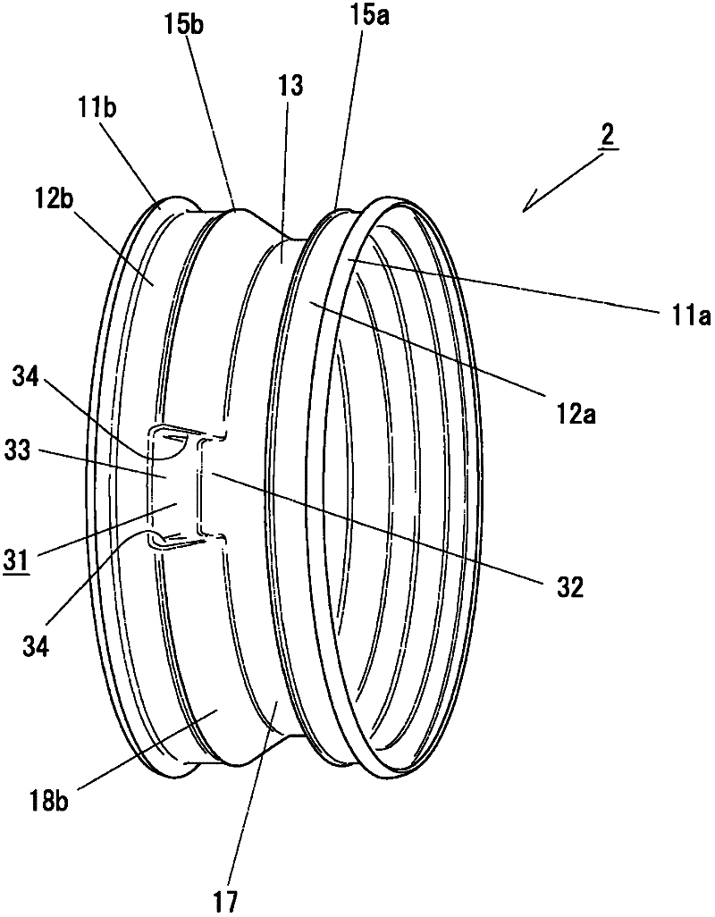
[0061] In Example 2, compared with the structure of the above-mentioned Example 1, it is the vehicle wheel 1 of the structure with a narrower rim width. Specifically, it is an automobile wheel 1 of a 13×3.50B type (or a 13×31 / 2J type). In addition, the automobile wheel 1 of the second embodiment has the same configuration as that of the first embodiment except for the rim 2 having a narrow rim width, so the same reference numerals are used for the respective components, and the description thereof is omitted.

[0062] The rim 2 of the second embodiment has a rim width of 3.5 inches, and the width p of the well bottom 17 of the well portion 13 in the front and rear directions is about 22 mm. In addition, the valve 100 with an air pressure detection device has the same structure as that of the above-mentioned first embodiment, and adopts the same dimensions.

[0063] The rim 2 of this embodiment 2, such as Figure 5 , 6 As shown, the well recessed portion 13 provided in the b...

Embodiment 3

[0067] In the automobile wheel 51 of the third embodiment, such as Figures 7 to 9 As shown, it is configured such that a well recessed portion 61 is formed on the front side well wall portion 58 a of the rim 52 . Here, the rim 52 has the same structure as that of the first embodiment except that the well-well portion 58a of the well-well portion 53 is provided with the well-well recessed portion 61 on the front side, so the same components are denoted by the same reference numerals. Its description is omitted. In addition, the spoke 3 has the same structure as that of the above-described first embodiment, and the same components are denoted by the same reference numerals, and the description thereof will be omitted.

[0068] In the above-described rim 52 , the well recessed portion 61 is formed in a portion of the front side well wall portion 58 a of the well portion 53 where the valve hole 59 is formed so as to be recessed toward the front. In addition, the well recessed p...


PUM


Abstract

Disclosed is an automobile wheel configured so that a well recess is formed at the area at the back side well wall of the well of the wheel rim that faces a valve hole, said well recess receding toward the back along a well bottom of the well. Through this configuration, the vibration that is generated by the centrifugal force of an air valve equipped with an air pressure detection device when the vehicle is moving can be suppressed due to the shape of the well recess, and stable driving of the automobile and comfortable riding are thus improved. The same effect is also demonstrated when an automobile wheel is configured so that a well recess is formed at the area at the front side well wall of the well where the valve hole is to be formed, said well recess receding toward the front along the well bottom of the well of the wheel rim so that the front side portion of the air pressure detection device of the air valve can be fit therein.

Description

technical field [0001] The present invention relates to an automobile wheel including a spoke connected to an axle and a rim that supports a tire. Background technique [0002] In automobile wheels, there is a two-piece structure by fitting and welding a roughly cylindrical rim and a roughly disk-shaped spoke. Here, the rim is generally formed by a rolling process in which a rectangular metal plate is bent into a cylindrical body and then pressed from the inside and outside with a predetermined die. On the other hand, the spokes are generally formed by pressing a metal plate having a substantially square shape. By welding these individually formed rims and spokes into one piece, a two-piece construction vehicle wheel is produced. [0003] The above-mentioned rim includes front and rear bead seating surfaces that support a tire bead, and a groove-shaped well portion formed between the front and rear bead seating surfaces in the circumferential direction. Further, the well ...

Claims


Application Information

Patent Timeline
Patent Type & Authority Applications(China)
IPC IPC(8): B60B21/00B60B21/12B60C23/04
CPCB60B3/044B60B21/12B60B21/026B60C23/0494
Inventor 浜田和男
Owner CENTRAL MOTOR WHEEL CO LTD
Why Eureka
Try Eureka