Patch radiator

A radiator and patch technology, applied in the field of patch radiators, can solve problems such as narrow band of patch antennas, and achieve the effects of low dielectric loss factor, size reduction, and broadband improvement.

Active Publication Date: 2014-07-30
KATHREIN AUTOMOTIVE GMBH
View PDF11 Cites 16 Cited by
  • Summary
  • Abstract
  • Description
  • Claims
  • Application Information

AI Technical Summary

Problems solved by technology

But the patch antenna is generally extremely narrowband based on the slot

Method used


Image

  • Patch radiator
  • Patch radiator
  • Patch radiator

Examples


Embodiment Construction

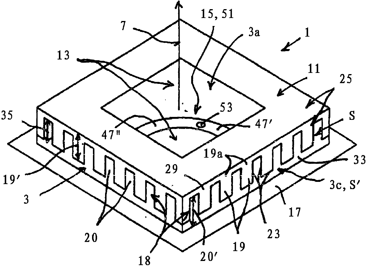
[0080] exist figure 1 The basic structure of the patch antenna 1 is shown in , and shown in a schematic three-dimensional view.

[0081] This is preferably a circularly polarized patch antenna.

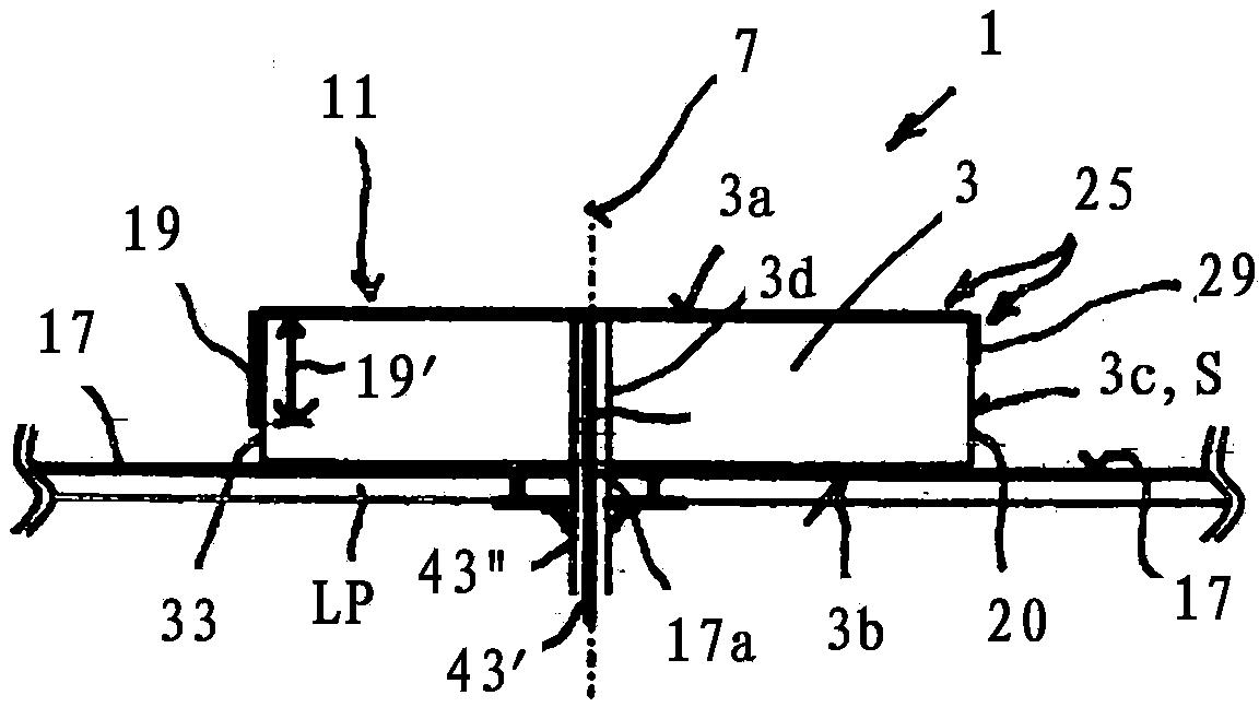
[0082] Patch Antennas Included - As From According to figure 2 The cross-sectional view of is visible - a dielectric body 3, which is sometimes also referred to as a substrate in the following.

[0083] The three-dimensional base comprises an upper side 3a, a lower side 3b and surrounding side walls 3c, which are sometimes also referred to below as side surfaces 3c.

[0084] In the illustrated embodiment, the side wall or side surface 3c is oriented extending perpendicularly to the base upper side 3a or lower side 3b and thus parallel to a central axis 7 which passes vertically and centrally through the base upper and lower sides.

[0085] Instead of the term "side wall" 3c, the term "side surface space" S is sometimes used hereinafter because—as will be shown later—another design...


PUM


Abstract

An improved patch radiator is characterised by the following additional features: the radiator surface (11) is designed as an annular and/or frame-shaped radiator surface (11), extending around a recess area (13), - the radiator surface (11) is extended so as to transition into the lateral surfaces or lateral walls (3c), and on the lateral surfaces or lateral walls (3c), a lateral surface radiator structure (18) electrically connected to the radiator surface (11) is formed, comprising, in the peripheral direction of the lateral surfaces or lateral walls (3c), lateral radiator surface sections (19), between which electrically non-conductive recess areas (20) are provided.

Description

technical field [0001] The invention relates to a patch radiator according to the preamble of claim 1 of the main patent DE 102011117690.3. Background technique [0002] In principle, patch radiators are fully disclosed, for example, by DE 10 2004 016 158 A1. [0003] Such patch radiators are known to comprise a dielectric substrate comprising an upper side, an underside and surrounding wall sections, ie side surfaces. In this respect it is a three-dimensional body, which in most applications is square in plan view. In this case, a closed, likewise square radiating surface is formed on the upper side, which is fed via a supply line extending perpendicularly thereto through the entire substrate and supplied from the lower side. [0004] Provided on the underside is a ground plane which also protrudes, if necessary, from the outer contour of the base, which ground plane is provided with a corresponding hole-like recess through which the feed conductor extends to the undersid...

Claims


Application Information

Patent Timeline
Patent Type & Authority Applications(China)
IPC IPC(8): H01Q9/04H01Q5/00
CPCH01Q9/0414H01Q9/0428H01Q9/0442H01Q9/0464H01Q9/04H01Q1/38
Inventor N·多布里克
Owner KATHREIN AUTOMOTIVE GMBH
Why Eureka
Try Eureka