Eureka AIR delivers breakthrough ideas for toughest innovation challenges, trusted by R&D personnel around the world.

Broadband electromagnetic dipole circularly polarized antenna

An electromagnetic dipole and circularly polarized antenna technology, which is applied to the antenna grounding device, the structural connection of the antenna grounding switch, the structural form of the radiating element, etc., can solve the problem that the performance indicators of the electromagnetic dipole circularly polarized antenna are not ideal and difficult to meet. Practical application requirements, high cost and loss, etc., to achieve good broadband performance, good consistency, and good broadband performance.

Active Publication Date: 2021-03-12
NANJING UNIV OF SCI & TECH
View PDF4 Cites 2 Cited by
  • Summary
  • Abstract
  • Description
  • Claims
  • Application Information

AI Technical Summary

Problems solved by technology

[0004]At present, most of the electromagnetic dipole antenna designs are mainly realized by loading external power dividing circuits and phase shifting networks, and it is necessary to design a relatively complicated feeding network. On the one hand, the The antenna structure is more complex, on the other hand, it also leads to higher cost and loss
However, some performance indicators of the existing single-fed electromagnetic dipole circularly polarized antenna are not ideal enough to meet the needs of practical applications.

Method used


Image

  • Broadband electromagnetic dipole circularly polarized antenna
  • Broadband electromagnetic dipole circularly polarized antenna
  • Broadband electromagnetic dipole circularly polarized antenna

Examples


Embodiment

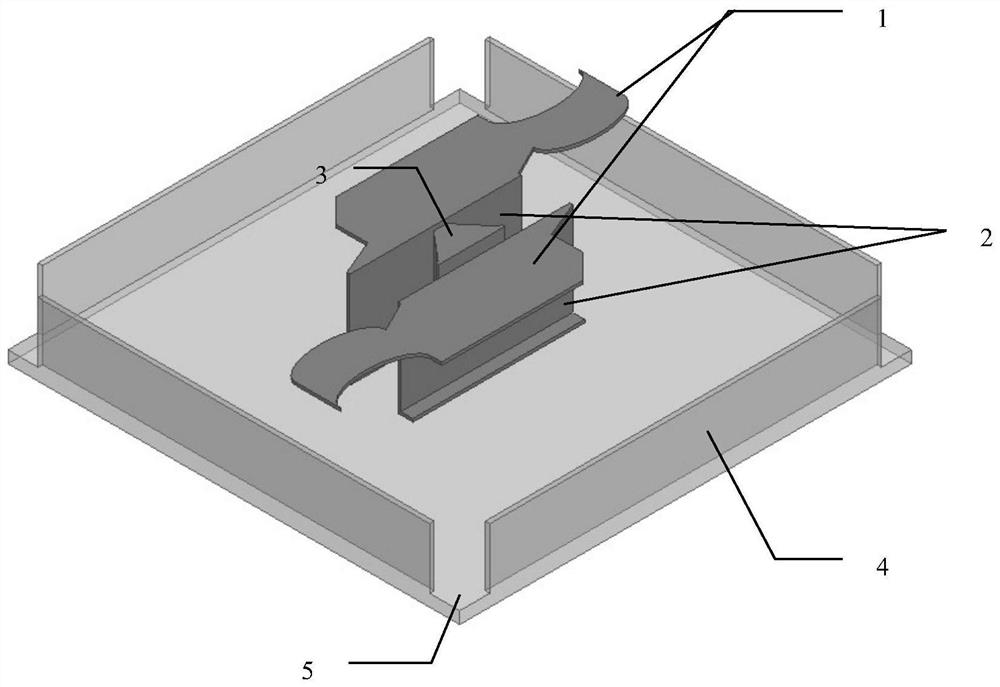
[0031] A broadband electromagnetic dipole circularly polarized antenna, comprising an electric dipole 1, a magnetic dipole 2, a Γ-shaped feed sheet 3, a metal wall 4, a floor 5 and a coaxial connector, the electric dipole 1 is composed of a pair of metal sheets parallel to the floor 5, and the magnetic dipole 2 is composed of a pair of metal sheets placed perpendicular to the floor 5 and short-circuited with the floor 5; the electric dipole 1 is arranged on the magnetic dipole The Γ-shaped feed piece 3 is connected to the inner conductor of the coaxial connector installed on the back of the floor 5, and is coupled to the electric dipole 1 and the magnetic dipole 2 at the same time. Electrically, the metal wall 4 is arranged at the center of the four sides of the floor 5 .

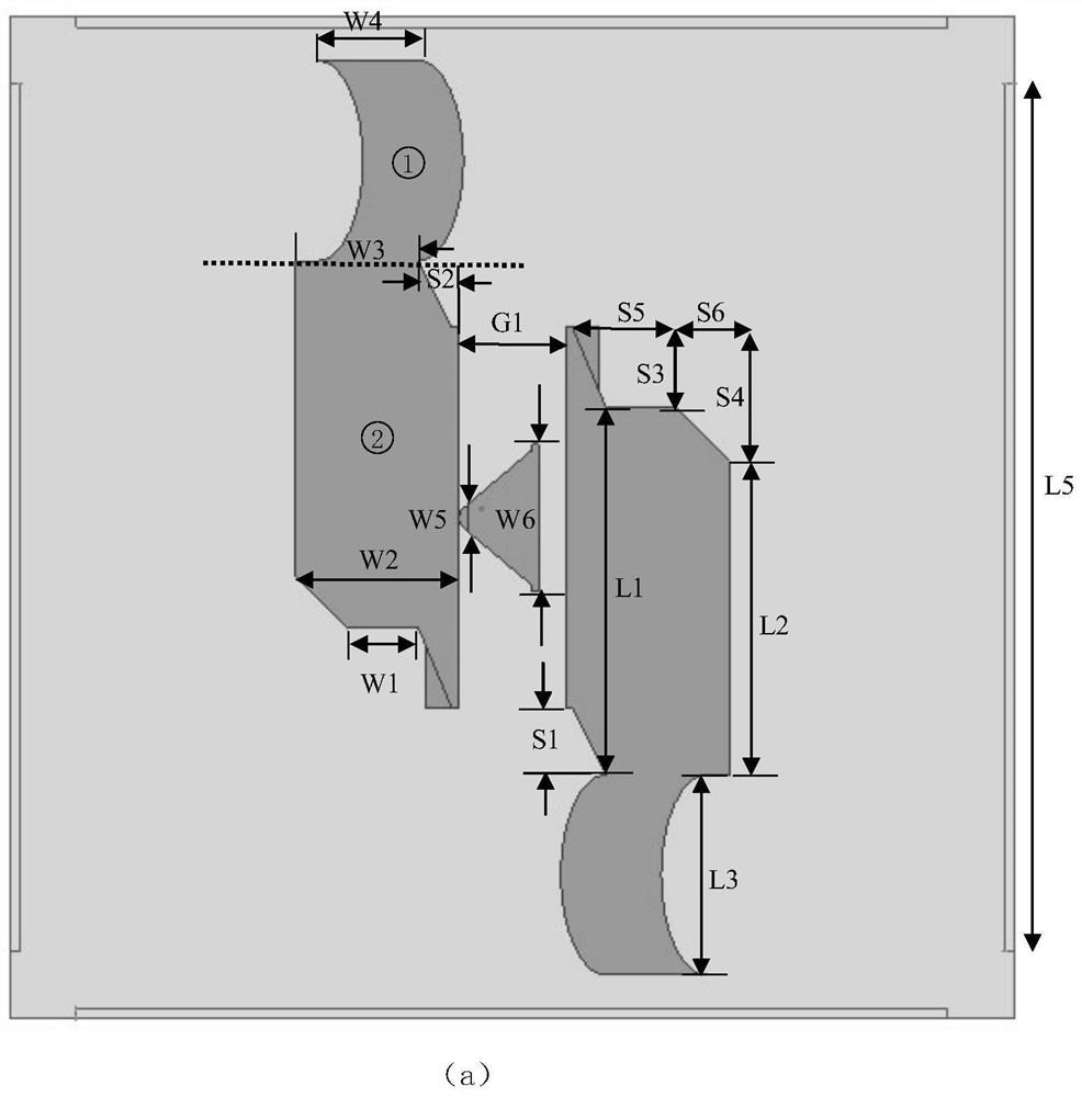
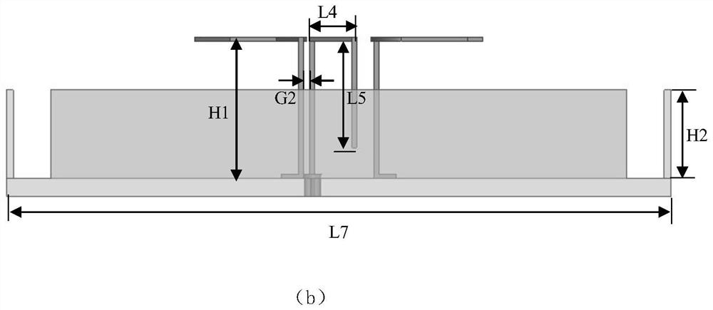
[0032] figure 2 A schematic diagram of the size of the present invention is given, the floor 5 is a square copper plate with side length L5=15mm, the Γ-shaped feed sheet 3 includes a first metal sheet, a ...


PUM


Abstract

The invention discloses a broadband electromagnetic dipole circularly polarized antenna, and the antenna comprises an electric dipole, a magnetic dipole, an inverted L-shaped feed sheet, a metal wall,a floor and a coaxial connector; the electric dipole consists of a pair of metal sheets parallel to the floor, and the magnetic dipole consists of a pair of metal sheets which are vertical to the floor and are short-circuited with the floor; the electric dipoles are arranged on the magnetic dipoles and are in central symmetry about the center of the floor; the inverted L-shaped feed sheet is arranged on the floor, is connected with an inner conductor of the coaxial connector arranged on the back surface of the floor and is used for coupling and feeding the electric dipole and the magnetic dipole, and the metal walls are arranged in the centers of four sides of the floor. The broadband electromagnetic dipole circularly polarized antenna has better broadband performance, and is convenient to process and good in mechanical stability.

Description

technical field [0001] The invention relates to the field of microwave antennas, in particular to a broadband electromagnetic dipole circularly polarized antenna. Background technique [0002] As the amount of data transmitted and interacted in modern wireless communication continues to increase, the system needs a wider operating frequency band to ensure a smooth link, and narrowband antennas can no longer meet the needs of practical applications. In addition, in many communication systems, it is necessary to receive or transmit multiple signals. When multiple antennas are used, the mutual coupling effect between the antennas will affect the communication quality of the system. Using broadband antennas can solve the above problems. The circularly polarized antenna can receive any polarized wave, and the radiation wave of the circularly polarized antenna can be received by any linearly polarized antenna. The use of circularly polarized antennas can make the forms of the tra...

Claims


Application Information

Patent Timeline
Patent Type & Authority Applications(China)
IPC IPC(8): H01Q1/36H01Q1/48H01Q1/50
CPCH01Q1/36H01Q1/48H01Q1/50
Inventor 齐世山瞿安俐吴文尚伦申
Owner NANJING UNIV OF SCI & TECH
Why Eureka
Eureka Blog
Learn More