Versatile wideband phased array fed reflector antenna system and method for varying antenna system beamwidth

Active Publication Date: 2009-08-13
LOCKHEED MARTIN CORP
View PDF6 Cites 4 Cited by
  • Summary
  • Abstract
  • Description
  • Claims
  • Application Information

AI Technical Summary

Benefits of technology

[0004]The present invention solves the foregoing problems by providing an antenna system with variable beamwidth that enjoys excellent wideband performance. This antenna system addresses the co-channel problem from a s

Problems solved by technology

As the demands placed on these communications systems increase, the distance between geographic areas that utiliz

Method used


Image

  • Versatile wideband phased array fed reflector antenna system and method for varying antenna system beamwidth
  • Versatile wideband phased array fed reflector antenna system and method for varying antenna system beamwidth
  • Versatile wideband phased array fed reflector antenna system and method for varying antenna system beamwidth

Examples


Embodiment Construction

[0021]In the following detailed description, numerous specific details are set forth to provide a full understanding of the present invention. It will be apparent, however, to one ordinarily skilled in the art that the present invention may be practiced without some of these specific details. In other instances, well-known structures and techniques have not been shown in detail to avoid unnecessarily obscuring the present invention.

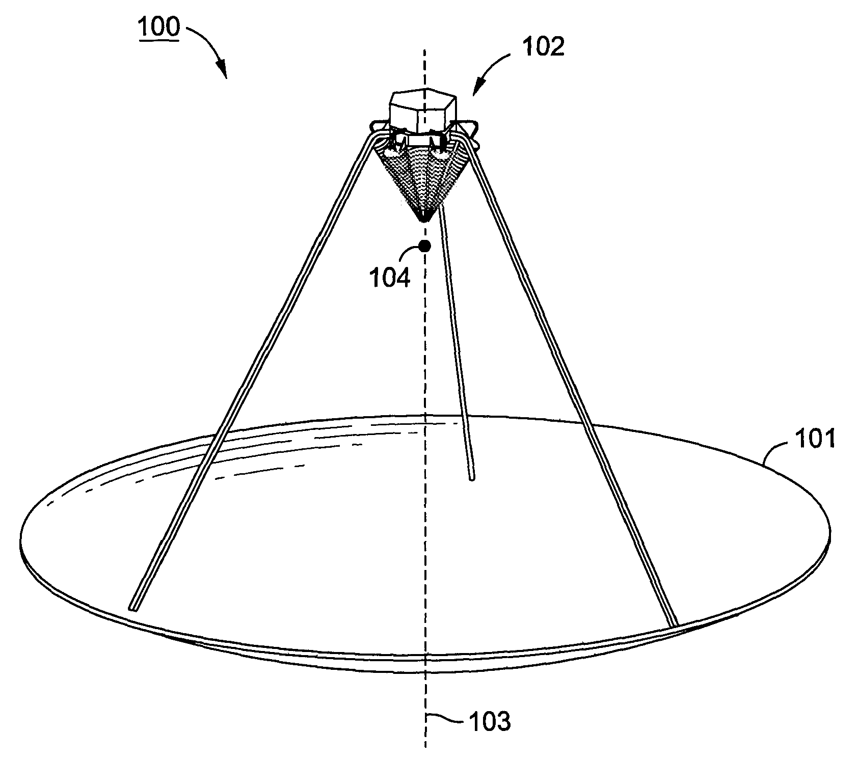
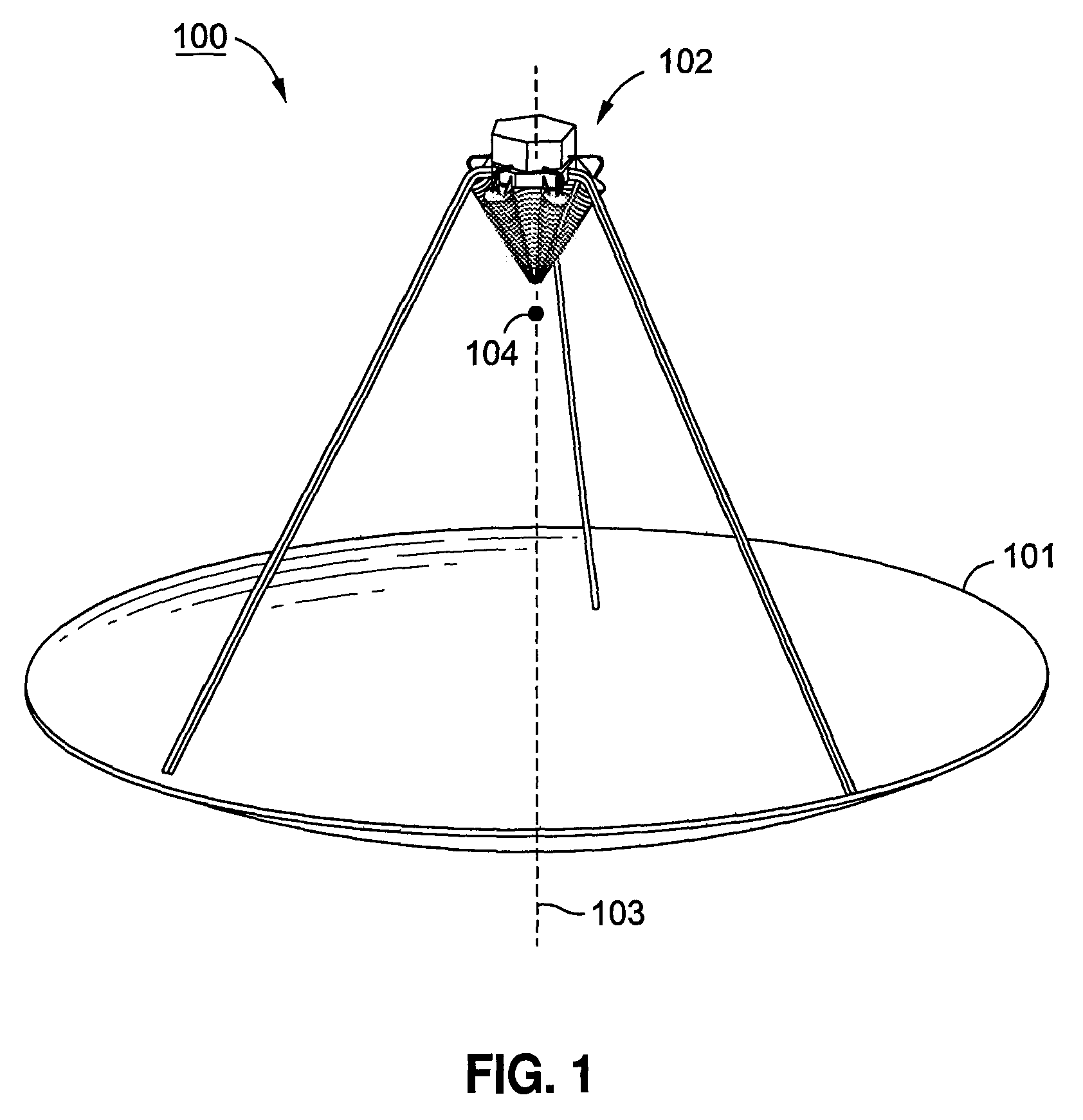
[0022]FIG. 1 illustrates an antenna system 100 in accordance with one embodiment of the present invention. Antenna system 100 includes a parabolic reflector 101 and an array 102 of feed elements disposed on an axis 103 of reflector 101. The feed elements of array 102 are disposed such that each feed element is the same distance in wavelengths from the focal point 104 of reflector 101 as every other feed element.

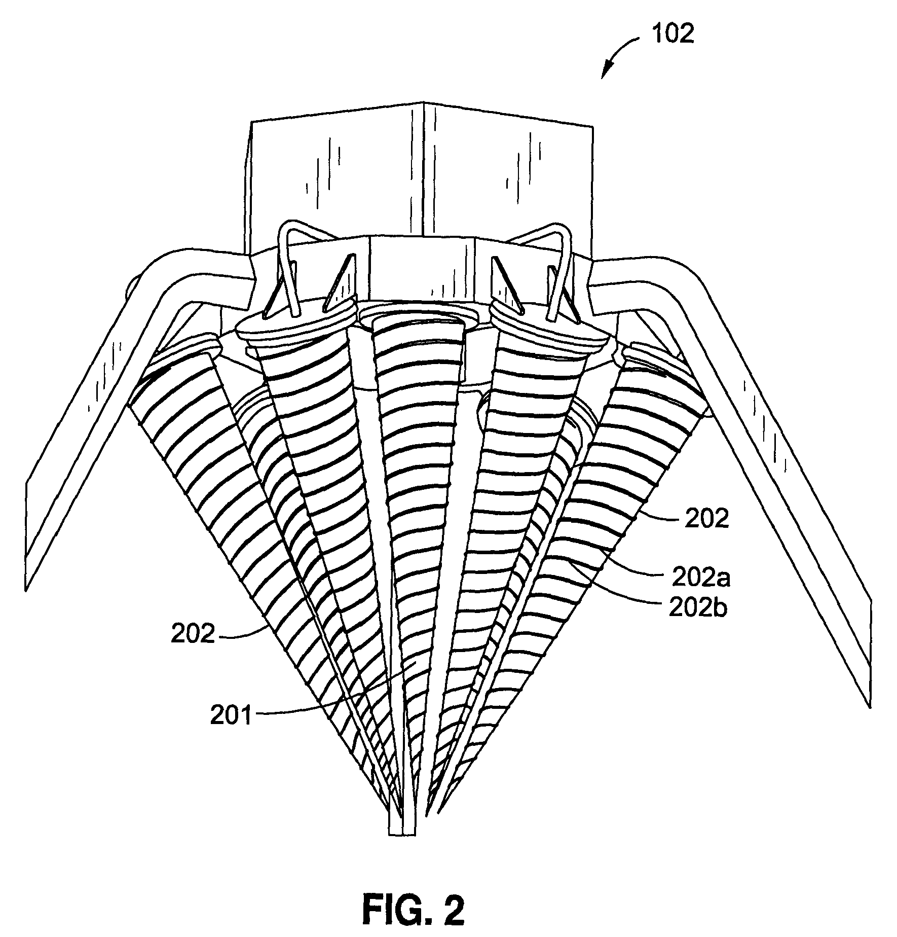
[0023]FIG. 2 illustrates array 102 of feed elements in greater detail, in accordance with one aspect of the present invention. Array 102 includes ...


PUM


Abstract

An antenna system includes a reflector having a focal point, and a phased array having feed elements. Each feed element is disposed a same distance from the focal point of the reflector. A method for varying the beamwidth of an antenna system includes providing the antenna system with a reflector having a focal point and feed elements disposed a same distance from the focal point. The feed elements includes one or more inner feed elements and one or more outer feed elements. The method further includes adjusting relative amplitudes of the inner feed elements and the outer feed elements to adjust the beamwidth of the antenna system. An antenna system includes a parabolic reflector having a focal point, and a phased array having one or more inner feed elements and one or more outer feed elements. Each of the feed elements is disposed a same distance in wavelengths from the focal point, and is oriented towards the focal point.

Description

STATEMENT REGARDING FEDERALLY SPONSORED RESEARCH OR DEVELOPMENT[0001]Not applicable.FIELD OF THE INVENTION[0002]The present invention generally relates to antenna systems and, in particular, relates to versatile wideband phased array fed reflector antenna systems and methods for varying antenna system beamwidth.BACKGROUND OF THE INVENTION[0003]Many communications systems manage co-channel interference (e.g., multiple signals that simultaneously use the same RF channel) via several techniques, such as power control, spatial separation, orthogonal coding and antenna directivity. As the demands placed on these communications systems increase, the distance between geographic areas that utilize overlapping RF channels shrinks. Accordingly, it is desirable to provide communications systems with variable beamwidth that provide service to smaller geographical areas to reduce overlapping coverage. Many variable beamwidth systems, however, suffer from poor wideband performance.SUMMARY OF THE ...

Claims


Application Information

Patent Timeline
IPC IPC(8): H01Q19/12
CPCH01Q3/28H01Q21/067H01Q19/17
Inventor WATSON, TIMOTHY D.CENCICH, SR., THOMAS P.MCDONNELL, JEANNETTE C.
Owner LOCKHEED MARTIN CORP
Why Eureka
Try Eureka