
Tray stacking machine achieving high-position replacement

A technology for palletizing machines and pallets, which is applied in the field of high-position palletizing palletizers, and can solve problems such as long pallet replacement time, affecting palletizing efficiency of palletizing machines, and speeding up pallet replacement.

Active Publication Date: 2014-08-06
GUANGXI LIYUANBAO SCI & TECH
View PDF6 Cites 9 Cited by
  • Summary
  • Abstract
  • Description
  • Claims
  • Application Information

AI Technical Summary

Problems solved by technology

[0005] The purpose of the present invention is to solve the defects that existing automatic palletizers take too long to replace pallets and affect the improvement of the palletizing efficiency of the palletizer, and provide a new type of pallet high-position replacement palletizer that allows it to pass through pallets. The elevator and the pallet high-level transfer device can realize the high-position replacement of the pallet under the palletizing door, speed up the replacement speed of the pallet, shorten the replacement time of the pallet, and improve the palletizing efficiency of the palletizer

Method used


Image

  • Tray stacking machine achieving high-position replacement
  • Tray stacking machine achieving high-position replacement
  • Tray stacking machine achieving high-position replacement

Examples


Embodiment Construction

[0031] In order to further explain the technical means and effects of the present invention to achieve the intended purpose of the invention, the specific implementation, structure, Features and their functions are described in detail below.

[0032] The aforementioned and other technical contents, features and effects of the present invention will be clearly presented in the following detailed description of preferred embodiments with reference to the drawings. Through the description of specific embodiments, a more in-depth and specific understanding of the technical means and effects adopted by the present invention to achieve the intended purpose can be obtained. However, the attached drawings are only for reference and description, and are not used to explain the present invention. be restricted.

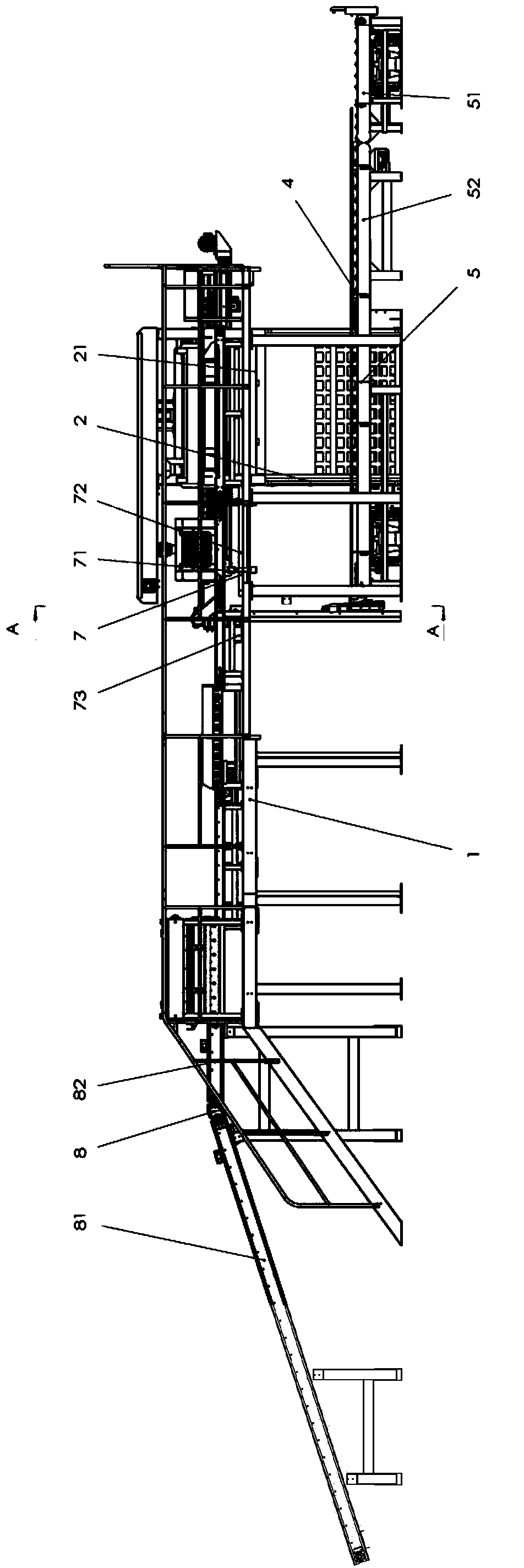
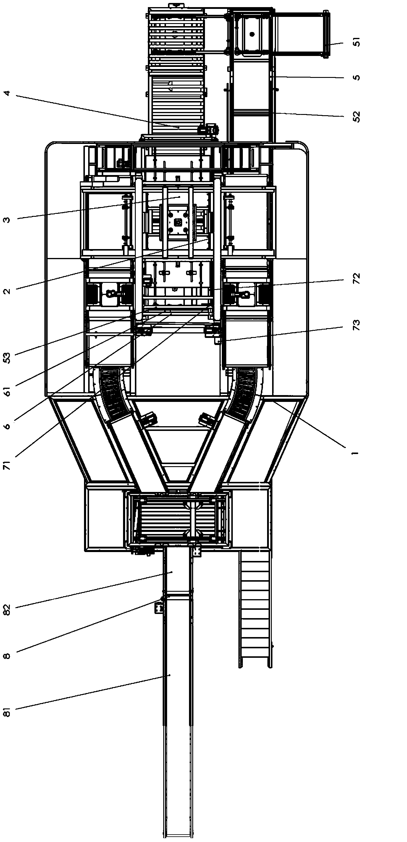
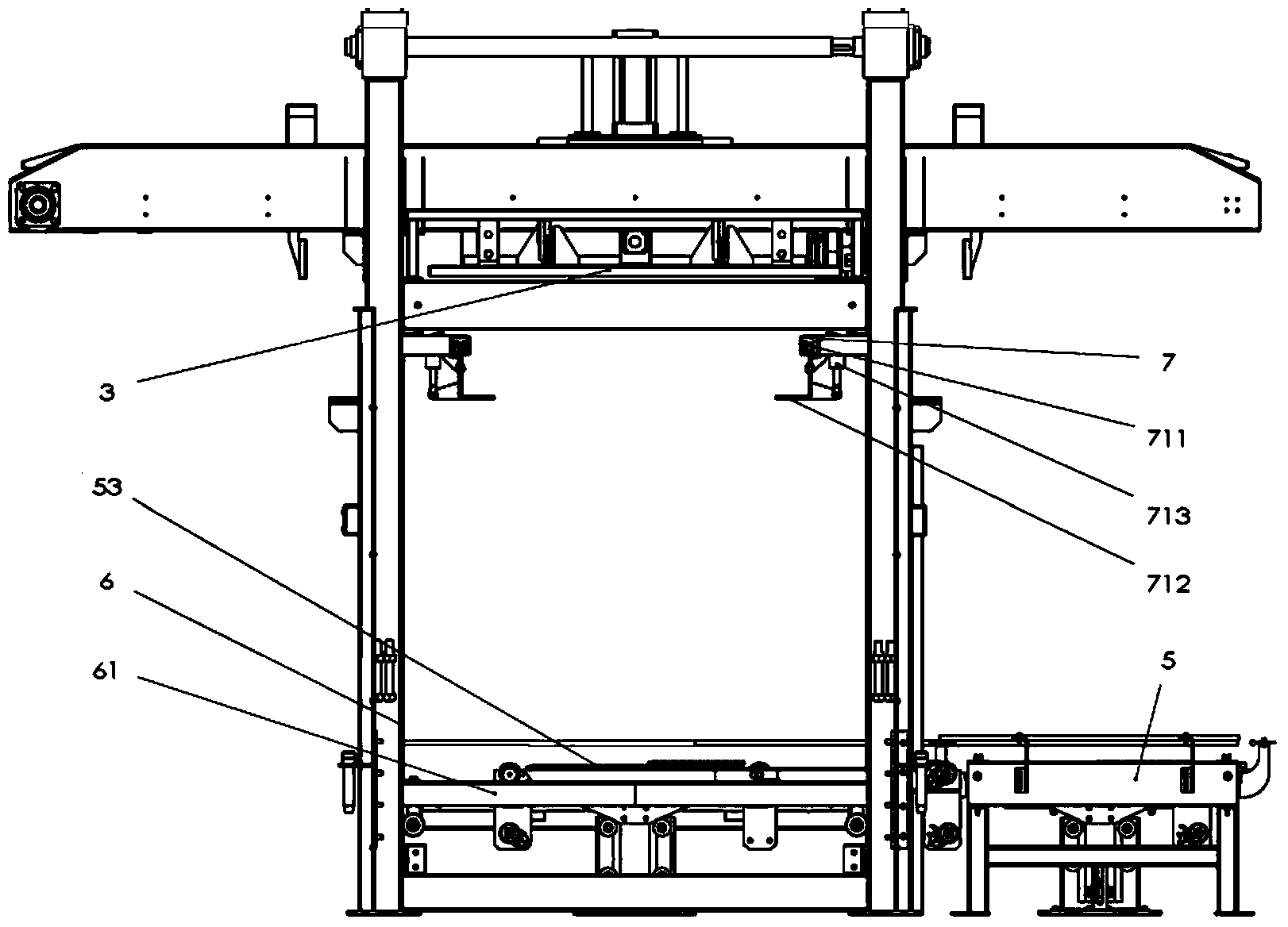
[0033] see figure 1 and figure 2 as shown, figure 1 It is a schematic front view of the structure of a preferred embodiment of a high pallet replacement palletizer of the ...


PUM


Abstract

The invention discloses a tray stacking machine achieving high-position replacement. The machine comprises a high platform, a stacking lifting machine, a stacking layering door, a stacked tray conveying machine, a tray low-position conveying device, a tray lifting machine and a tray high-position transferring device, wherein the tray lifting machine is installed on the lower portion of the high platform and is connected with the high platform and is located behind the stacking lifting machine and above the tray low-position conveying device; the tray high-position transferring device is installed on the upper portion of the tray lifting machine and below the stacking layering door; when the stacking machine works, trays sequentially pass the tray lifting machine and the tray high-position transferring device to be conveyed from the tray low-position conveying device to below the stacking layering door, so that high-position replacement is achieved. Accordingly, the stacking machine can accelerate the replacement speed of the trays, shortens replacement time of the trays and improves stacking efficiency.

Description

technical field [0001] The invention belongs to the field of automatic palletizing equipment, in particular to a high-position palletizing machine for pallets. Background technique [0002] In the production of modern chemical, food, feed, fertilizer and other industries, automatic palletizers have been increasingly used in the palletizing of bagged products. At present, there are roughly two main types of automatic palletizers commonly used in production practice, namely high-position single-line palletizers and high-position double-line high-speed palletizers. The average palletizing efficiency of high-position single-line palletizers is 1200 bags / The average efficiency of the high-position double-line high-speed palletizer can reach about 2000 bags / hour. However, some large-scale chemical, food, feed, fertilizer and other production lines have very high production capacity, and often a single production line requires the supporting automatic palletizing equipment to hav...

Claims


Application Information

Patent Timeline
IPC IPC(8): B65G57/26B65G61/00
Inventor 邓秀泉胡国宜
Owner GUANGXI LIYUANBAO SCI & TECH
Learn More