Batching cylinder

A cloth reel and body technology, applied in the field of cloth reel, can solve problems such as easy detachment of the cloth reel, small amount of cloth to be wound, and not tightly wound cloth reel, and achieve simple structure, smooth winding, and around the tight effect

Inactive Publication Date: 2014-08-06
CHONGQING YUBI TEXTILE
View PDF0 Cites 8 Cited by
  • Summary
  • Abstract
  • Description
  • Claims
  • Application Information

AI Technical Summary

Problems solved by technology

[0002] Ordinary cloth rolls are generally only composed of a single cloth roll body and a rotating shaft. When using a cloth roll to wind cloth, the cloth is not wound tightly on the roll, resulting in a small amount of wound cloth, and because the cloth Wrinkles make the cloth winding part flat, and the cloth roll wound on the cloth drum is easy to come out

Method used


Image

  • Batching cylinder
  • Batching cylinder

Examples


Embodiment Construction

[0009] Below in conjunction with accompanying drawing, the present invention is described in detail.

[0010] In order to make the object, technical solution and advantages of the present invention clearer, the present invention will be further described in detail below in conjunction with the accompanying drawings and embodiments. It should be understood that the specific embodiments described here are only used to explain the present invention, not to limit the present invention.

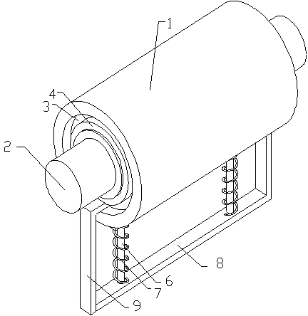
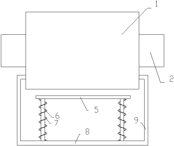
[0011] Such as figure 1 , figure 2 As shown, a cloth roll includes a cloth roll body 1 and a rotating shaft 2, both ends of the cloth roll body 1 are provided with circular grooves 3, the rotating shaft 2 passes through the cloth roll body 1, and The cloth roll body 1 is fixedly connected, and the two ends of the rotating shaft 2 pass through the circular grooves 3 at the two ends of the cloth rolling body 1 respectively. The two ends of the rotating shaft 2 are symmetrically provided with a be...


PUM


Abstract

The invention discloses a batching cylinder which comprises a batching cylinder body and a rotary shaft. Circular grooves are formed in the two ends of the batching cylinder body respectively. The rotary shaft penetrates through the batching cylinder body and is fixedly connected with the batching cylinder body. The two ends of the rotary shaft penetrate out of the circular grooves in the two ends of the batching cylinder body respectively. The two ends of the rotary shaft are symmetrically provided with bearings. The rotary shaft fixedly penetrates through the bearings in a sleeved mode. The bearings are located in the circular grooves. A leveling device is arranged above the batching cylinder body and comprises a pressing board, a telescopic rod, a spring, a transverse board and supports. The telescopic rod is located between the end of the pressing board and the end of the transverse board. The two ends of the telescopic rod are fixedly connected with the pressing board and the transverse board respectively. The telescopic rod is sleeved with the spring and the two ends of the spring abut against the pressing board and the transverse board respectively. Each end of the transverse board is fixedly connected with one end of the corresponding support. The other end of each support is fixedly connected with the outer ring of the corresponding bearing through a connecting block. The batching cylinder is simple in structure and compact and flat in batching operation.

Description

technical field [0001] The invention relates to a cloth roll. Background technique [0002] Ordinary cloth rolls are generally only composed of a single cloth roll body and a rotating shaft. When using a cloth roll to wind cloth, the cloth is not wound tightly on the roll, resulting in a small amount of wound cloth, and because the cloth The folds make the cloth winding part flat, and the cloth roll wound on the cloth drum is easy to come off. Contents of the invention [0003] The purpose of the present invention is to provide a cloth roll with simple structure, tight and smooth winding for the above problems. [0004] The technical solution adopted in the present invention is as follows: a cloth roll, including a cloth roll body and a rotating shaft, both ends of the cloth roll body are provided with circular grooves, the rotating shaft passes through the cloth roll body, It is fixedly connected with the body of the cloth roll, and the two ends of the rotating shaft pa...

Claims


Application Information

Patent Timeline
Patent Type & Authority Applications(China)
IPC IPC(8): B65H18/26
Inventor 万明全
Owner CHONGQING YUBI TEXTILE
Why Eureka
Try Eureka