A coil winding device and method of winding an elongate member

A long, component technology, applied in the field of coil winding devices, to achieve the effects of minimizing the amount of work hardening, minimizing the three-dimensional space, and reducing the free space

Inactive Publication Date: 2012-05-23
SMS MEER
View PDF7 Cites 1 Cited by
  • Summary
  • Abstract
  • Description
  • Claims
  • Application Information

AI Technical Summary

Problems solved by technology

[0008] However, the second method has the disadvantage of imposing significant work hardening on the tube when it is wound into a coil

Method used


Image

  • A coil winding device and method of winding an elongate member
  • A coil winding device and method of winding an elongate member
  • A coil winding device and method of winding an elongate member

Examples


Embodiment Construction

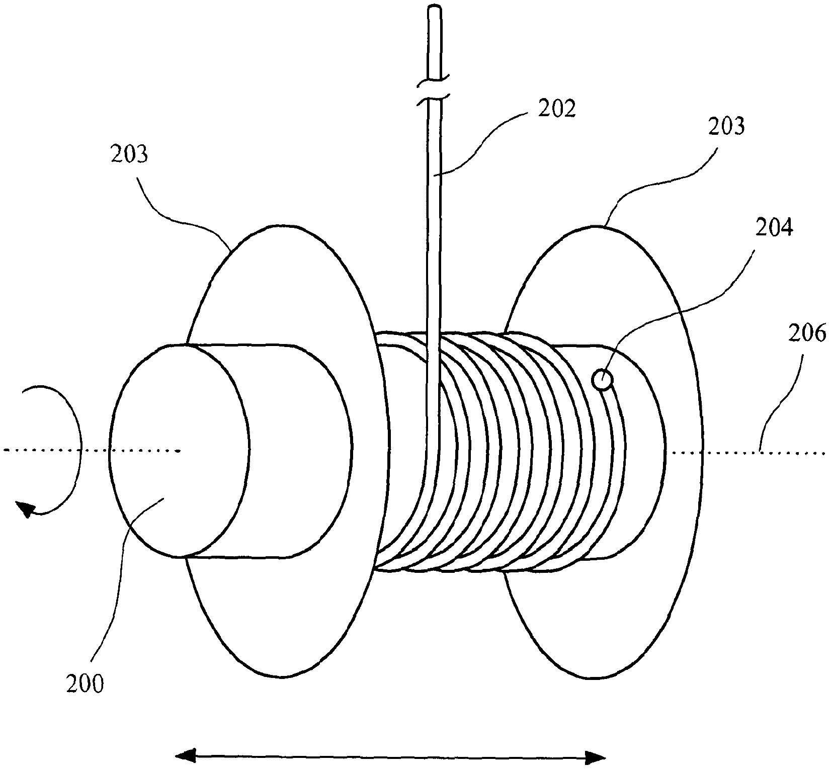
[0049] refer to Figure 4A , 4B and 4C, a winding device 300 is provided for winding an elongate member, such as a metal tube 303, into a coil. The winding device 300 has a first body portion 302 and a second body portion 304 each preferably disc-shaped. The first body portion 302 is adapted to rotate about a first axis 306 . The winding device 300 has fixing means for fixing a part of the tube 303 extending from the guide member 305 to the first body part 302 . The metal pipe passes through the guide member 305 and utilizes Figure 7 The automatic clamping system shown is connected to a purging unit in the first body portion 302 . The second body portion 304 has a plurality of hairs 308 extending from the second body portion 304 in the direction of the first body portion 302 and a cylindrically shaped member 309 . Preferably, the length of the hairs 308 and shaping member 309 is about twice the diameter of the tube 303 to be wound into a coil by the device 300 . The shap...


PUM


Abstract

A device (300) for winding a tube (303) into a coil. The device having a first body portion (302) adapted to rotate about a first axis (306), fixing means for fixing a portion of a tube (303) to the first body portion (302), and force application means (308) for applying a force (310) to the tube (303) while it is being wound. The force (310) has first and second force components acting in perpendicular first and second directions (312, 314) respectively, for restricting movement of the tube (303) in directions parallel with the first and second directions. The first force component (312) acts towards the first body portion (302).

Description

technical field [0001] The present invention relates to a coil winding device and in particular but not exclusively to a device for coiling fully annealed tube with minimal work hardening. Background technique [0002] The annealing process is commonly used on copper tubes to improve the properties of the tubes used in products such as refrigeration units. Referring to FIG. 1 , coils of hard copper tube stored in baskets 10 are processed through an annealing line 12 to remove any work hardening before being recoiled about the axis of rotation, forming multi-layer coils of annealed copper. Tube 14. However, the process of recoiling the copper tubing after the annealing process itself introduces work hardening into the copper. [0003] A first method of winding a fully annealed tube into a coil is shown in Figures 2a and 2b, which show a set of rollers 100 the distance between which can be adjusted. The tube 102 can be wound into a coil by such rollers 100 by rolling the tu...

Claims


Application Information

Patent Timeline
Patent Type & Authority Applications(China)
IPC IPC(8): B21C47/06B21C47/32B65H54/02
CPCB21C47/326B21C47/3491B65H54/2851B65H2701/33B21C47/06B65H57/00
Inventor 托尼·科德
Owner SMS MEER
Why Eureka
Try Eureka