Fireproof transformer

A technology for transformers and closed covers, which is applied in the field of transformers and can solve problems such as safety accidents, heat accumulation, and coil heating

Active Publication Date: 2014-08-13
郴州成瑞电子有限公司
View PDF4 Cites 5 Cited by
  • Summary
  • Abstract
  • Description
  • Claims
  • Application Information

AI Technical Summary

Problems solved by technology

In order to avoid leakage or other accidents, an insulating pad is usually installed between the magnetic core and the coil frame, but the magnetic core will generate heat during operation, which will cause the aging o

Method used


Image

  • Fireproof transformer

Examples


Embodiment Construction

[0016] The present invention will be specifically introduced below in conjunction with the accompanying drawings and specific embodiments.

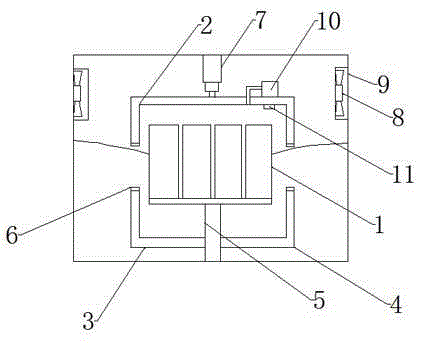
[0017] A fireproof transformer, including: a coil frame 1 wound with a coil, a magnetic core placed in the central through hole of the coil frame 1, and a closure assembly that can automatically close the coil frame 1, a moving assembly connected to the closure assembly, and fixed to the closure assembly on the suction parts.

[0018] The closing assembly consists of: a first closing cover 2 movable on the upper end of the coil frame 1, a second closing cover 3 and a third closing cover 4 movable on the lower end of the coil frame 1, and a first closing cover 2 and a second closing cover 3 are provided. 1. The sealing member 6 at the joint between the third closing covers 4; as a preferred method, the sealing member 6 is a rubber pad. It should be noted that as long as the sealing member 6 is a material or structure that can play a sealin...


PUM


Abstract

The invention discloses a fireproof transformer which comprises a coil rack with a coil wound on the rack, a magnetic core arranged in a through hole in the center of the coil rack, a closing assembly capable of automatically closing the coil rack, a movable assembly connected with the closing assembly and an air extraction piece fixed on the closing assembly. A closing cover of a closable coil and an air pump capable of extracting air are provided, a sealed environment can be provided for the coil when fire happens, fire is prevented, and accidents are avoided.

Description

technical field [0001] An electrical device, especially a transformer. Background technique [0002] A transformer according to the prior art mainly has a form in which a primary coil and a secondary coil are sequentially wound on a single bobbin, and a core is coupled to the bobbin through a through hole of the bobbin. In order to avoid leakage or other accidents, an insulating pad is usually installed between the magnetic core and the coil frame, but the magnetic core will generate heat during operation, which will promote the aging of the insulating pad, and the coil will also generate heat, and the heat will accumulate, which will promote the aging of the coil. Cause local fire, safety accident takes place, prior art has not solved such problem yet. Contents of the invention [0003] In order to solve the deficiencies of the prior art, the object of the present invention is to provide a closed cover that can close the coil and an air pump for extracting gas, which can...

Claims


Application Information

Patent Timeline
IPC IPC(8): H01F27/30H01F27/02H01F27/08
Inventor 任育文
Owner 郴州成瑞电子有限公司
Why Eureka
Try Eureka