
Reactive power compensation control method, device and system

A compensation control and power system technology, applied in reactive power compensation, reactive power adjustment/elimination/compensation, etc., can solve problems such as slow dynamic switching, achieve fast reactive power compensation, solve slow dynamic switching, and ensure stability Effect

Active Publication Date: 2016-12-07
河南德威特电气有限公司
View PDF4 Cites 0 Cited by
  • Summary
  • Abstract
  • Description
  • Claims
  • Application Information

AI Technical Summary

Problems solved by technology

[0006] Aiming at the problem of slow dynamic switching of reactive power compensation methods in the related art, no effective solution has been proposed so far. Therefore, the main purpose of the present invention is to provide a reactive power compensation control method, device and system to solve the above problems

Method used


Image

  • Reactive power compensation control method, device and system
  • Reactive power compensation control method, device and system
  • Reactive power compensation control method, device and system

Examples


Embodiment Construction

[0024] First of all, some nouns or terms appearing in the process of describing the embodiments of the present invention are applicable to the following explanations:

[0025] In order to enable those skilled in the art to better understand the solutions of the present invention, the following will clearly and completely describe the technical solutions in the embodiments of the present invention in conjunction with the drawings in the embodiments of the present invention. Obviously, the described embodiments are only It is an embodiment of a part of the present invention, but not all embodiments. Based on the embodiments of the present invention, all other embodiments obtained by persons of ordinary skill in the art without making creative efforts shall fall within the protection scope of the present invention.

[0026] It should be noted that the terms "first" and "second" in the description and claims of the present invention and the above drawings are used to distinguish s...


PUM


Abstract

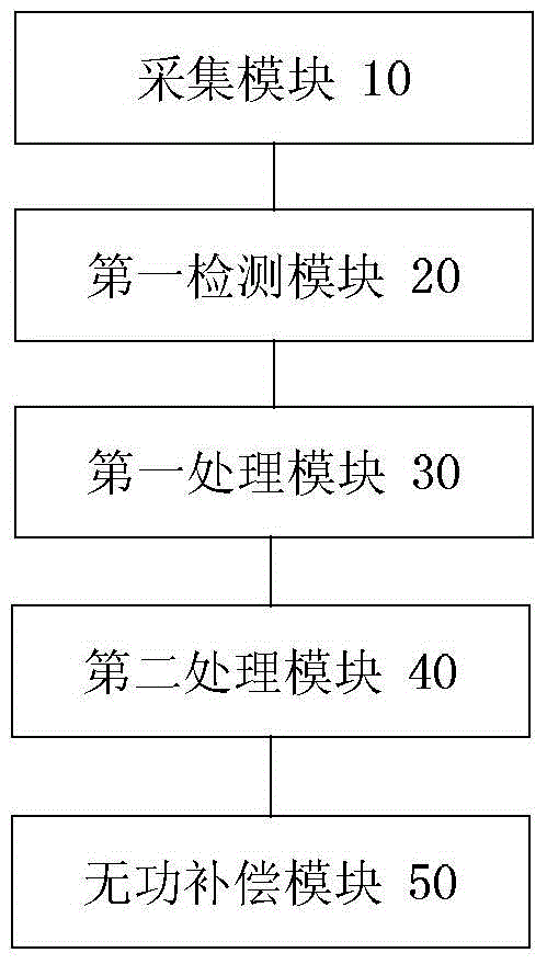
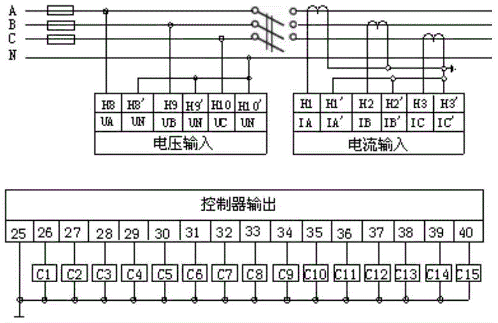
The invention discloses a reactive compensation control method, device and system. The method comprises the steps of collecting electric signals of an electric system in real time, detecting whether the electric signals contain jump signals or not, determining sudden load change data of the electric system under the situation that the electric signals contain the jump signals, calculating reactive power of the electric system according to the sudden load change data, calculating reactive power of the electric system at preset time intervals under the situation that the electric signals contain no jump signals, and conducting reactive compensation on the electric system according to the reactive power. By the adoption of the reactive compensation control method, device and system, the problem that dynamic switching of an existing reactive compensation mode is slow is solved, reactive compensation can be carried out on the system when loads of the electric system change, and therefore stability of the system can be ensured.

Description

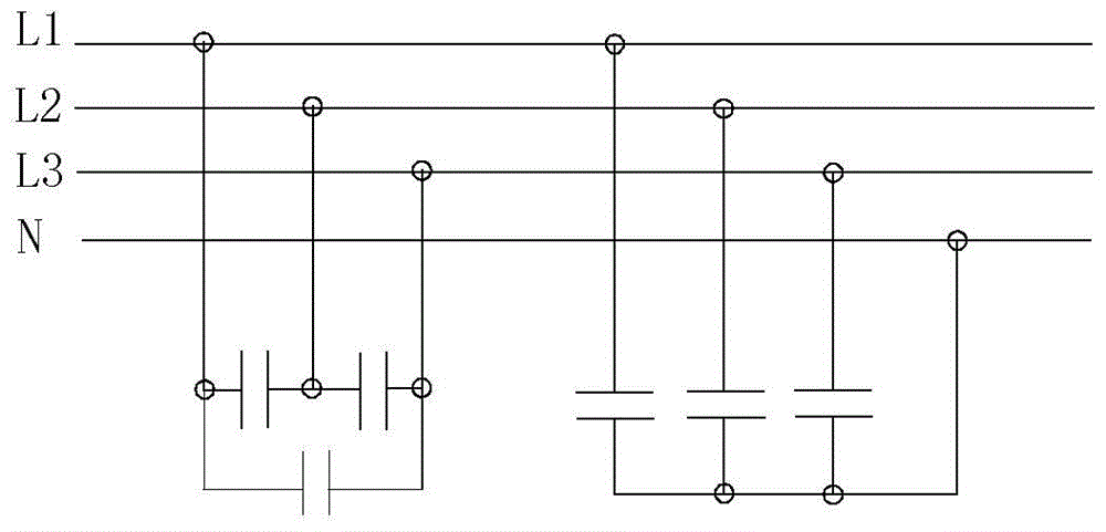
technical field [0001] The present invention relates to the field of power system control, in particular to a reactive power compensation control method, device and system. Background technique [0002] Such as figure 1 As shown, the current reactive power compensation is mainly realized through phase separation, joint compensation or separate blend compensation. figure 1 In the compensation method shown, the power distribution cabinets used for reactive power compensation are all under centralized control, and the switching of capacitors is also compensated in a centralized way. Because of the centralized control, the total power factor of the system can also be improved, but The response speed of switching capacitors is slow, but it can’t do anything about the rapid changes of the impact load. During the fast “run-stop” period of the load, the capacitors cannot be switched normally, because it cannot be compensated quickly, so the reactive power consumption of such loads ...

Claims


Application Information

Patent Timeline
Patent Type & Authority Patents(China)
IPC IPC(8): H02J3/18
CPCY02E40/30
Inventor 王敬仁李慧勇赵长兵张鉴高龙集刘国营常红旗侯红民薛利民欧阳强
Owner 河南德威特电气有限公司
Learn More