Method for detecting continuity of wiring impedance of PCB based on rapid pulse response
A detection method and fast pulse technology, applied in the field of computer communication, can solve problems such as the inability of impedance consistency and continuity, and achieve the effect of realizing wiring reliability, ensuring high efficiency and low cost
- Summary
- Abstract
- Description
- Claims
- Application Information
AI Technical Summary
Problems solved by technology
Method used
Image
Examples
Embodiment
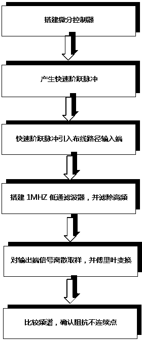
[0024] The advantages and design content of the fast impulse response-based PCB wiring impedance continuity detection method of the present invention will be described in detail below through an embodiment:
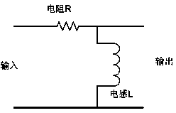
[0025] In this implementation, first build a differential controller, adjust the differential controller (as attached figure 1 As shown), the differential link generates a fast step pulse with a rise time of 2ns, and the pulse level amplitude is 1V. In the existing differential controller, adjusting the differential link is to control the inductance value of the inductor to delay the rising edge of the signal Shorten, in order to prevent the impact of the pulse on the devices on the main board, the level and amplitude of the pulse are controlled at 1V;
[0026] When the main board is powered off, the above-mentioned fast step pulse is directly introduced into the input end of the wiring path to be tested on the PCB, and the length from the differential controller to the i...
PUM
 Abstract
Description
Claims
Application Information
 - R&D
- Intellectual Property
- Life Sciences
- Materials
- Tech Scout
- Unparalleled Data Quality
- Higher Quality Content
- 60% Fewer Hallucinations
Browse by: Latest US Patents, China's latest patents, Technical Efficacy Thesaurus, Application Domain, Technology Topic, Popular Technical Reports.
© 2025 PatSnap. All rights reserved.Legal|Privacy policy|Modern Slavery Act Transparency Statement|Sitemap|About US| Contact US: help@patsnap.com


