Gap eliminating device and seamless splicing display device

A technology for eliminating seams and display areas, applied in the direction of identification devices, instruments, etc., can solve the problems of sudden changes in light intensity at seams, affecting the effect of splicing display, and unable to achieve smooth transition of light emitted from the LCD frame area and light emitted from the display area.

Inactive Publication Date: 2014-08-20
GUANGDONG VTRON TECH CO LTD
View PDF9 Cites 7 Cited by
  • Summary
  • Abstract
  • Description
  • Claims
  • Application Information

AI Technical Summary

Problems solved by technology

However, none of these traditional methods can achieve a smooth transition between the light emitted from the LCD frame area and the light emitted from the display area, and there will be a sudden change in light intensity at the seam during the implementation process (such as figure 1 shown), which will inevitably cause visual dark lines and affect the splicing display effect

Method used


Image

  • Gap eliminating device and seamless splicing display device
  • Gap eliminating device and seamless splicing display device
  • Gap eliminating device and seamless splicing display device

Examples


Embodiment 1

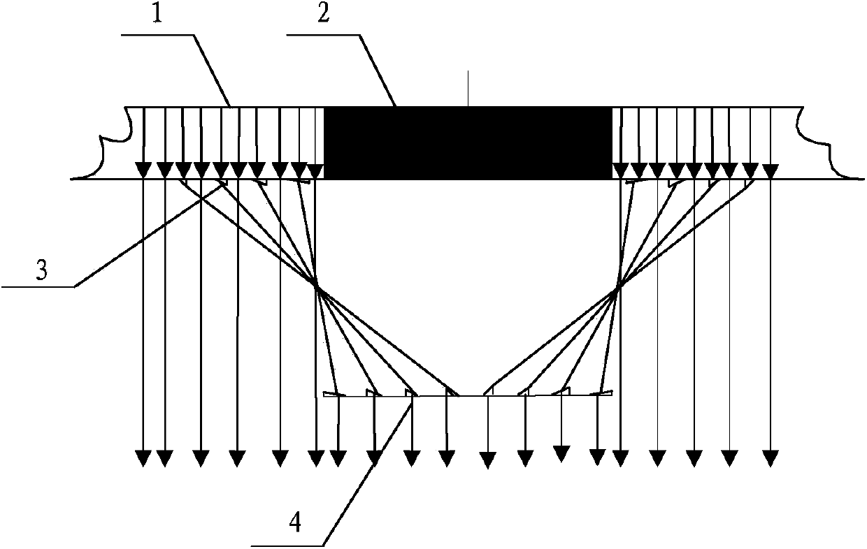
[0027] Refer to 2, which is a schematic diagram of the principle of Embodiment 1 of the seam elimination device of the present invention. see image 3 Shown is a schematic structural view of Embodiment 1 of the seam eliminating device of the present invention.

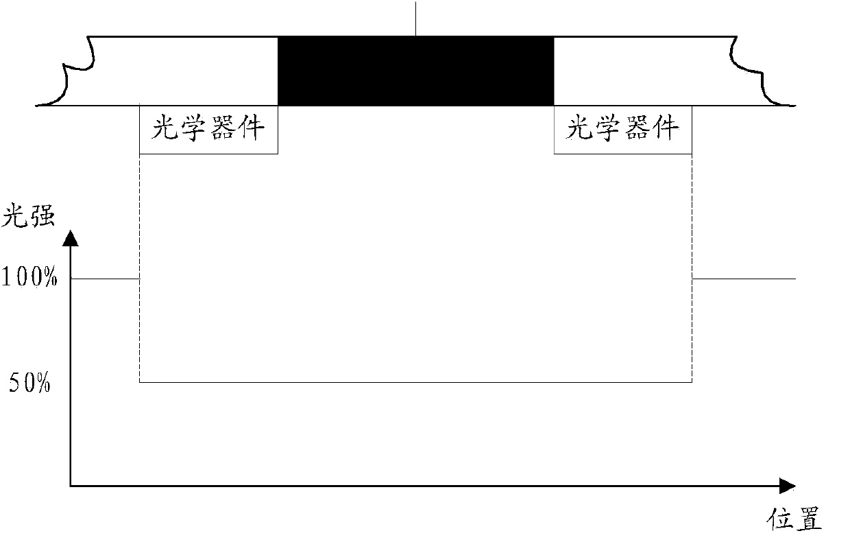
[0028] Such as figure 2 , image 3 As shown, the anti-seam device of Embodiment 1 includes a first optical assembly 3 arranged in front of the display area 1 of the display screen and a first optical assembly 3 arranged in front of the frame area 2 of the display screen and corresponding to the first optical assembly 3 second optical assembly 4;

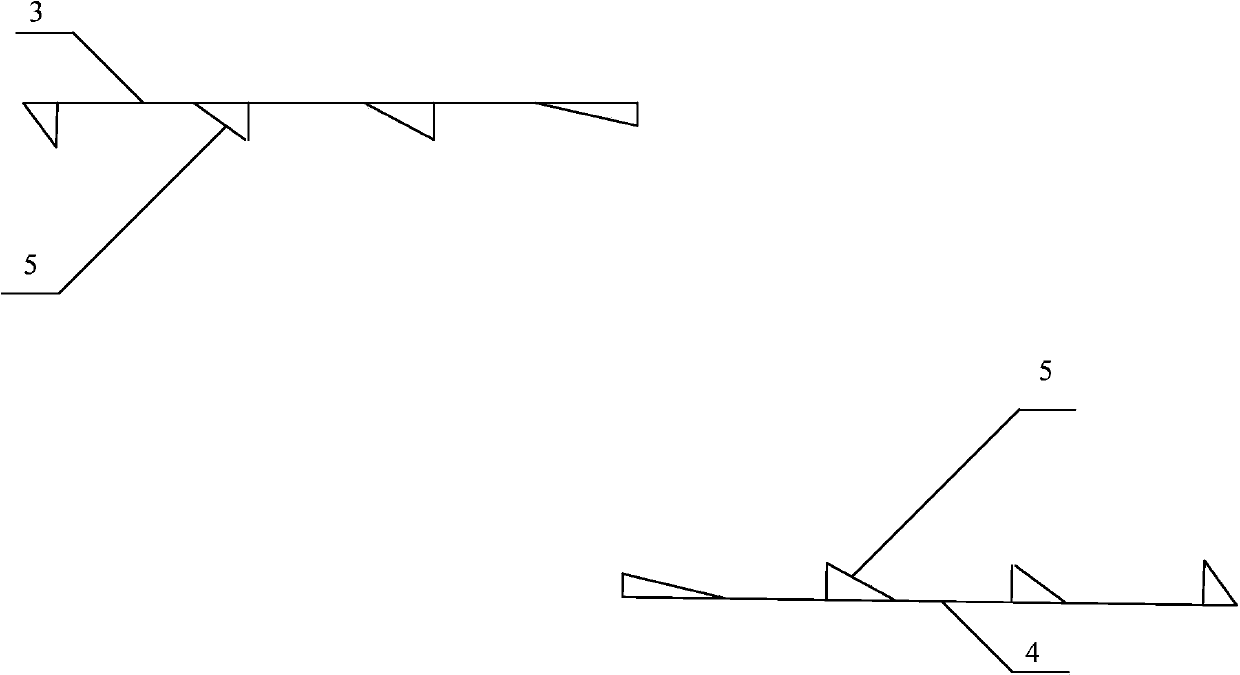
[0029] The widths of the first optical assembly 3 and the second optical assembly 4 are consistent with the width of the frame area 3, and both the first optical assembly 3 and the second optical assembly 4 include a plurality of first deflectors 5;

[0030] The first deflectors 5 of the first optical assembly 3 and the second optical assembly 4 are all arranged in a dir...

Embodiment 2

[0046] Refer to 5, which is a schematic diagram of the principle of Embodiment 2 of the seam elimination device of the present invention. see Figure 6 As shown, it is a structural schematic diagram of Embodiment 2 of the seam eliminating device of the present invention.

[0047] Such as Figure 5 , Figure 6 As shown, the anti-seam device in Embodiment 2 includes a third optical assembly 6 arranged in front of the display area 1 of the display screen and a first optical assembly 6 arranged in front of the frame area 2 of the display screen and corresponding to the third optical assembly 6 Four optical components 7;

[0048] The widths of the third optical assembly 6 and the fourth optical assembly 7 are consistent with the total width of the adjacent spliced ​​frame areas of the frame area 3, and the third optical assembly 6 and the fourth optical assembly 7 each include a plurality of second deflectors 8;

[0049] The second deflection members 8 of the third optical ass...


PUM


Abstract

The invention provides a gap eliminating device which comprises a first optical module arranged in front of a display area and a second optical module arranged in front of a frame area and corresponding to the first optical module. The first optical module and the second optical module are consistent to the frame area in width and comprise multiple first defection parts. The light emergence faces of the first defection parts are columnar faces. The gap eliminating device further comprises a first optical module arranged in front of the display area and a fourth optical module arranged in front of the frame area and corresponding to the third optical module. The widths of the third optical module and the fourth optical module are consistent to the total width of an adjacent splicing frame area, and the third optical module and the fourth optical module comprise multiple second defection part. The light emergence faces of the defection parts are planes. By adopting the gap eliminating device, smooth transition between emergence light of the frame area and emergence light of the display area can be achieved, and the display effect is enhanced.

Description

technical field [0001] The invention relates to the technical field of display screen splicing, in particular to a seam elimination device and a seamless splicing display device including the seam elimination device. Background technique [0002] In recent years, the large-screen splicing display market is still developing strongly, and it plays an important role in many industries and places such as electric power, coal, finance, transportation, and security. In the large-screen splicing display, LCD (Liquid Crystal Display) splicing display is favored by many merchants and customers due to its significant advantages such as light and thin size, low cost, large viewing angle, and low power consumption. However, due to process wiring and other reasons, the edge frame of the LCD is unavoidable, resulting in a seam of at least 5.5mm or more, which makes the screen divided and cannot be connected, which seriously affects the splicing display effect. [0003] In view of the abo...

Claims


Application Information

Patent Timeline
Patent Type & Authority Applications(China)
IPC IPC(8): G09F9/35
Inventor 王新星罗振华
Owner GUANGDONG VTRON TECH CO LTD
Why Eureka
Try Eureka