Apparatus for coating optical fiber

A cladding and optical fiber technology, which is applied in the field of cladding forming devices for optical fibers, can solve the problems of not considering temperature effects, weak light, and inability to re-form cladding.

Inactive Publication Date: 2005-03-09
FURUKAWA ELECTRIC CO LTD
View PDF0 Cites 0 Cited by
  • Summary
  • Abstract
  • Description
  • Claims
  • Application Information

AI Technical Summary

Problems solved by technology

However, this effect due to temperature is not considered in conventional recoaters
So it can happen that the light output from the light source 2 is not at all precisely controlled by the light output controller 1, for example, the light output from the light source 2 is too weak to reform the cladding

Method used


Image

  • Apparatus for coating optical fiber
  • Apparatus for coating optical fiber
  • Apparatus for coating optical fiber

Examples


Embodiment Construction

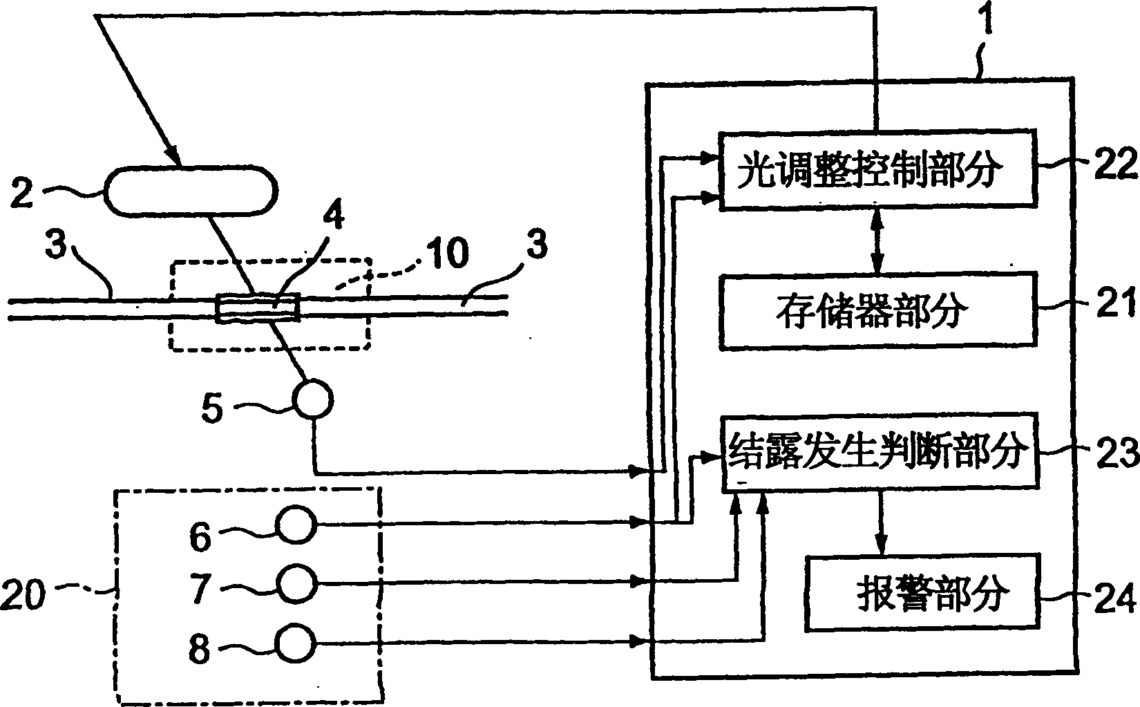
[0016] The present invention will be described in detail below on the basis of embodiment examples by referring to the accompanying drawings. In the following description of the examples of embodiments of the present invention, the same parts in the examples are denoted by the same reference numerals, and their repeated descriptions are omitted or simplified. figure 1 An example embodiment of the optical fiber cladding forming apparatus in the present invention will be described.

[0017] The coating forming means in this embodiment example is a recoverer having a light source 2 and a light receiver 5 similarly to the recoverer in the conventional example. This embodiment example is characterized by employing an environment sensor 20 for detecting the temperature of the environment including at least the temperature in the installation area of ​​the light source 2 and the light receiver 5 . In addition, this embodiment example is also characterized in that a light output con...


PUM


Abstract

An optical fiber coating forming device forms a coating of an ultraviolet light hardening type in an optical fiber by precisely controlling an ultraviolet light output of a light source. The optical fiber coating forming device has a light source (2) for irradiating ultraviolet light to resin for coating formation molded to a coating removing portion (4) of an optical fiber core wire (3), a light receiver (5) for detecting intensity of the ultraviolet light by receiving the ultraviolet light irradiated to the resin for coating formation from the light source (2), and an environmental sensor (20) for detecting environmental information. The environmental sensor (20) includes at least a temperature sensor (6) and selectively includes a humidity sensor (7) and an atmospheric pressure sensor (8). An optical output controller (1) feedback-controls the optical output of the light source (2) on the basis of the environmental information detected by the environmental sensor (20), the ultraviolet light intensity detected by the light receiver (5), and control data for controlling the optical output of the light source (2) based on the ultraviolet light intensity and the above environmental information.

Description

technical field [0001] The present invention relates to an optical fiber coating forming apparatus for forming a new coating in a coating-removed portion or the like of an optical fiber core wire. Background of the invention [0002] An optical fiber core formed by placing cladding on the periphery of an optical fiber is widely used in optical communication, optical measurement, and other fields. When the optical fiber cores are connected to each other, the coating of the connecting portion is usually stripped, for example, by clipping off its coating-removed portion with a connecting element, and the optical fiber cores are connected to each other. Also, as in the above case, after the coating is peeled off, the coating-removed parts are connected by welding, and a heat-shrinkable tube is wrapped around its connected part. [0003] For example, in recent years, with an increase in communication capacity and the like in the field of optical communication, an apparatus and e...

Claims


Application Information

Patent Timeline
Patent Type & Authority Patents(China)
IPC IPC(8): G02B6/44C03C25/12G02B6/24G02B6/38
CPCC03C25/12G02B6/2558
Inventor 小嶋秀和柴田俊生
Owner FURUKAWA ELECTRIC CO LTD
Why Eureka
Try Eureka