A hot core core making method and core making machine

A core making machine and hot core technology, which is applied to molding machines, manufacturing tools, casting and molding equipment, etc., can solve the problems of not making full use of the core making machine and reducing the core making efficiency, so as to improve the core making efficiency and save air circulation. time, waste reduction

Active Publication Date: 2016-01-13
SUZHOU MINGZHI TECH
View PDF5 Cites 0 Cited by
  • Summary
  • Abstract
  • Description
  • Claims
  • Application Information

AI Technical Summary

Problems solved by technology

[0006] The actions of each mechanism of the existing core making machine follow a single-step sequential action flow, and the sum of the running time of each action becomes the total running time of the equipment, which has a lot of empty cycle time, which cannot make full use of the core making machine and reduces the production cost. core efficiency

Method used


Image

  • A hot core core making method and core making machine
  • A hot core core making method and core making machine
  • A hot core core making method and core making machine

Examples


Embodiment 1

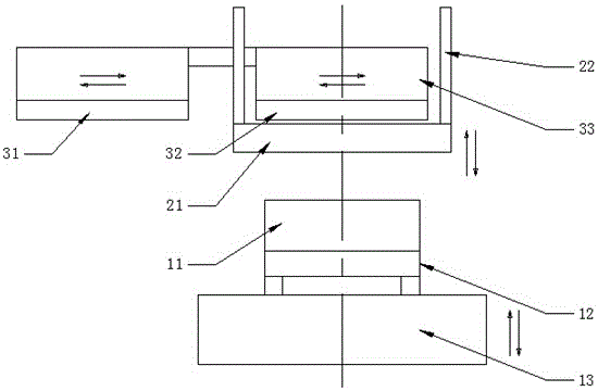
[0047] see figure 1 and figure 2 , as shown in the legend, a core making machine, including a lower core box device, an upper core box device, a sand ejecting core device and a hot core heating device (not shown in the figure), the lower core box device includes the following Core box 11, a lower mobile trolley 12 that can move in the horizontal direction, and a lift table 13 that can move in the vertical direction. The above-mentioned upper core box device includes an upper core box 21 and a lifting mechanism 22 that can move in the vertical direction , the above-mentioned sand-shooting and ejecting core device includes a sand-shooting mechanism 31, a core ejecting mechanism 32 and an upper mobile trolley 33 that can move in the horizontal direction, the lower core box 11 is connected to the lower mobile trolley 12, and the lower mobile trolley 12 is arranged on the lifting workbench 13, the lifting mechanism 22 is connected to the upper core box 21, the sand shooting mecha...

Embodiment 2

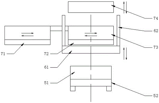
[0062] see image 3 and Figure 4 , as shown in the legend, a core making machine, including a lower core box device, an upper core box device, a sand ejecting core device and a hot core heating device (not shown in the figure), the lower core box device includes the following The core box 51 and the lower mobile trolley 52 that can move along the horizontal direction, the above-mentioned upper core box device includes an upper core box 61 and a lifting mechanism 62 that can move along the vertical direction, and the above-mentioned sand shooting device includes a sand shooting mechanism 71, A top core mechanism 72, an upper mobile trolley 73 that can move horizontally, and a pressing head 74 that can move vertically, the lower core box 51 is connected to the lower mobile trolley 52, and the lifting mechanism 62 is connected to the upper core On the box 61, the upper core box 61 is set opposite to the lower core box 51, the sand shooting mechanism 71 and the core pushing mech...

Embodiment 3

[0078] The rest is the same as the second embodiment, except that the above-mentioned upper mobile trolley is provided with an independent jacking mechanism and is not connected with the above-mentioned pressing head.


PUM


Abstract

The invention discloses a hot core making method and a hot core making machine. According to the hot core making method, the initial position and the end position of an upper core box are at the central position below a core ejection rod of a core ejection mechanism; according to one scheme, in a lifting-type machine model, a lower moving trolley drives a lower core box to move to a lower mold opening position; an upper moving trolley drives a sand shooting mechanism to a sand shooting position and drives the core ejection mechanism to a core ejection transition position synchronously; when a core is ejected by the core ejection mechanism, a lifting worktable drives the lower core box to move downwards to the lower mold opening position; a lifting mechanism delays and drives the upper core box to move downwards to the central position synchronously; in the hot core making machine, central position space and mold opening space are formed between the lower end of the core ejection rod of the core ejection mechanism and the upper end surface of the lower core box in sequence from top to bottom, so that space circulating time is shortened, the waste of equipment is reduced, and the core making efficiency is improved.

Description

technical field [0001] The invention relates to a core-making method and a core-making machine, in particular to a hot-core core-making method and a core-making machine. Background technique [0002] The core making machine (core shooting machine) mainly includes: the lower mobile trolley, the lower core box fixed on the lower mobile trolley, the upper mobile trolley, the sand shooting mechanism and core ejector mechanism fixed on the upper mobile trolley, the lifting mechanism and the The upper core box on the lifting mechanism, for different core making machine models, generally adopts a lifting workbench, through the lifting action of this mechanism to complete the core making production process, we call it the workbench lifting type, or use the upper part Press the pressing head tightly, and complete the core-making production process through the lifting action of this mechanism, which is called the upper pressing type. [0003] For the above two conventional models, in...

Claims


Application Information

Patent Timeline
Patent Type & Authority Patents(China)
IPC IPC(8): B22C15/23
Inventor 王鼎铭顾海兵徐磊磊
Owner SUZHOU MINGZHI TECH
Why Eureka
Try Eureka