Cold core or inorganic core manufacturing method and cold core or inorganic core manufacturing machine

A coreless and cold core technology, used in molding machines, manufacturing tools, casting and molding equipment, etc., can solve the problems of reducing core-making efficiency, unable to make full use of cold cores or machine-less core machines, etc., to improve core-making efficiency. , the effect of saving empty cycle time and reducing waste

Active Publication Date: 2014-08-27
SUZHOU MINGZHI TECH
View PDF7 Cites 3 Cited by
  • Summary
  • Abstract
  • Description
  • Claims
  • Application Information

AI Technical Summary

Problems solved by technology

[0006] The action of each mechanism of the existing cold core or inorganic core machine follows a single-step sequential action flow, and the sum of the running time of each action becomes the total running time of the equipment, which has a lot of empty cycle time, and cannot make full use of the cold core or Inorganic core machine reduces the efficiency of core making

Method used


Image

  • Cold core or inorganic core manufacturing method and cold core or inorganic core manufacturing machine
  • Cold core or inorganic core manufacturing method and cold core or inorganic core manufacturing machine
  • Cold core or inorganic core manufacturing method and cold core or inorganic core manufacturing machine

Examples


Embodiment 1

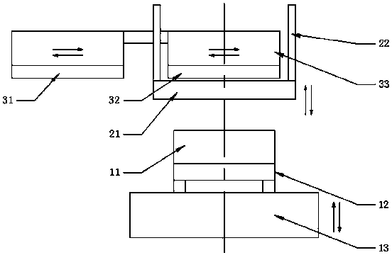
[0046] see figure 1 and figure 2 , as shown in the legend, a cold core or inorganic core machine, including a lower core box device, an upper core box device, a sand blasting core ejector device and a cold core inorganic gas generating device (not shown in the figure) The above-mentioned lower core box device comprises a lower core box 11, a lower mobile trolley 12 movable in the horizontal direction and a lifting workbench 13 movable in the vertical direction, and the above-mentioned upper core box device comprises an upper core box 21 and can move along the vertical direction. A lifting mechanism 22 that moves in the vertical direction. The above-mentioned sand-shooting and air-blowing core-jacking device includes a sand-shooting mechanism 31, a blowing / core-jacking mechanism 32 and an upper mobile trolley 33 that can move in the horizontal direction. The lower core box 11 is connected to On the lower mobile trolley 12, the lower mobile trolley 12 is set on the lifting tab...

Embodiment 2

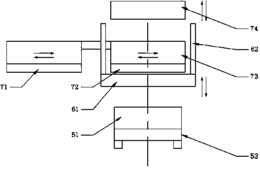
[0063] see image 3 and Figure 4 , as shown in the legend, a cold core or inorganic core machine, including a lower core box device, an upper core box device, a sand blasting core ejector device and a cold core inorganic gas generating device (not shown in the figure) The above-mentioned lower core box device includes a lower core box 51 and a lower mobile trolley 52 that can move in the horizontal direction, and the above-mentioned upper core box device includes an upper core box 61 and a lifting mechanism 62 that can move in the vertical direction. The blowing core device includes a sand shooting mechanism 71, a blowing / core pushing mechanism 72, an upper mobile trolley 73 that can move in the horizontal direction, and a pressing head 74 that can move in the vertical direction, and the sand shooting mechanism 71 and the blowing / core mechanism 72 are arranged on the upper mobile trolley 73, and the pressing head 74 is arranged on the sand-shooting mechanism 71 and the blowi...

Embodiment 3

[0078]The rest are the same as the first embodiment, the difference is that the lower surface of the above-mentioned sand-shooting mechanism is higher than the lower surface of the above-mentioned air-blowing / core ejector mechanism, and there is also a set between the above-mentioned fourth step and the fifth step. Step S1, the above step S1 is: the lifting table drives the lower core box up to the second upper mold closing position, and the lifting mechanism synchronously drives the upper core box up to the second upper mold closing position.


PUM


Abstract

The invention discloses a cold core or inorganic core manufacturing method and a cold core or inorganic core manufacturing machine. In the cold core or inorganic core manufacturing method, the initial position and the stop position of an upper core box is are the middle position below a core ejection rod of an air blowing / core ejection mechanism; one scheme is as follows: with a lifting type machine, a lower moving trolley drives a lower core box to a lower mold opening position, an upper moving trolley synchronously drives a sand ejection mechanism to a sand ejection position and drives the air blowing / core ejection mechanism to an air blowing / core ejection transit position; when the air blowing / core ejection mechanism ejects a core, a lifting work platform synchronously drives the lower core box to move downwards to the lower mold opening position, and a lifting mechanism delays to synchronously drive the upper core box to move downwards to the middle position; in a cold core or inorganic core manufacturing machine, a middle position space and a mold opening position are formed from top to bottom between the lower end of the core ejection rod of the air blowing / core ejection mechanism and the upper end surface of the lower core box, so that the idle loop time is saved, the equipment waste is reduced and the core manufacturing efficiency is improved.

Description

technical field [0001] The invention relates to a core making method and a core making machine, in particular to a cold core or inorganic core making method and a core making machine. Background technique [0002] Cold core or inorganic core machine (core shooter) mainly includes: lower mobile trolley, lower core box fixed on the lower mobile trolley, upper mobile trolley, sand shooting mechanism fixed on the upper mobile trolley and blowing / core ejector Mechanism, lifting mechanism and the upper core box fixed on the lifting mechanism, for different cold core or inorganic core machine models, generally use a lifting table, through the lifting action of this mechanism to complete the core production process, we call it The workbench lift type model, or the upper part is used to press the pressing head, and the core-making production process is completed through the lifting action of this mechanism, which is called the upper pressure type model. [0003] For the above two co...

Claims


Application Information

Patent Timeline
Patent Type & Authority Applications(China)
IPC IPC(8): B22C15/23
Inventor 王鼎铭顾海兵徐磊磊
Owner SUZHOU MINGZHI TECH
Why Eureka
Try Eureka