
Method for hoisting ud prefabricated part of trailing edge of wind power blade into main form shell layup

A technology for wind power generation blades and prefabricated parts, which is applied in the field of hoisting UD prefabricated parts at the trailing edge of wind power generation blades into the main formwork shell laying field, which can solve problems such as difficult fixing, unusable, complex shapes, etc.

Active Publication Date: 2016-04-13
广东明阳新能源材料科技有限公司
View PDF5 Cites 0 Cited by
  • Summary
  • Abstract
  • Description
  • Claims
  • Application Information

AI Technical Summary

Problems solved by technology

At present, the newly developed 6MW blade, whose trailing edge UD is a whole, has a complex shape and cannot be manufactured by the previous method. It needs to be manufactured in advance by prefabricated parts, and it is hoisted into the main mold layer when the shell is laid.
When the rear edge UD prefabricated parts are hoisted into the main form shell layer, in order to avoid affecting the laid glass fiber cloth and core material, it needs to be hoisted and placed in place once to avoid repeated placement and placement. The UD prefabricated parts have been adjusted too much, so the requirements for hoisting and the state of the trailing UD prefabricated parts are very high. point), the state of the rear UD prefabricated part is not easy to guarantee during hoisting, and it is prone to torsion, which cannot match the main mold layup; at the same time, limited by the shape of the rear UD prefabricated It is not easy to fix between layers, and the fixing method should also avoid the impact on the subsequent vacuum bagging process, which is very difficult

Method used


Image

  • Method for hoisting ud prefabricated part of trailing edge of wind power blade into main form shell layup
  • Method for hoisting ud prefabricated part of trailing edge of wind power blade into main form shell layup
  • Method for hoisting ud prefabricated part of trailing edge of wind power blade into main form shell layup

Examples


Embodiment Construction

[0024] The present invention will be further described below in conjunction with specific examples.

[0025] The method for hoisting the trailing edge UD prefabricated part of the wind power generation blade into the main formwork shell layer described in this embodiment is as follows:

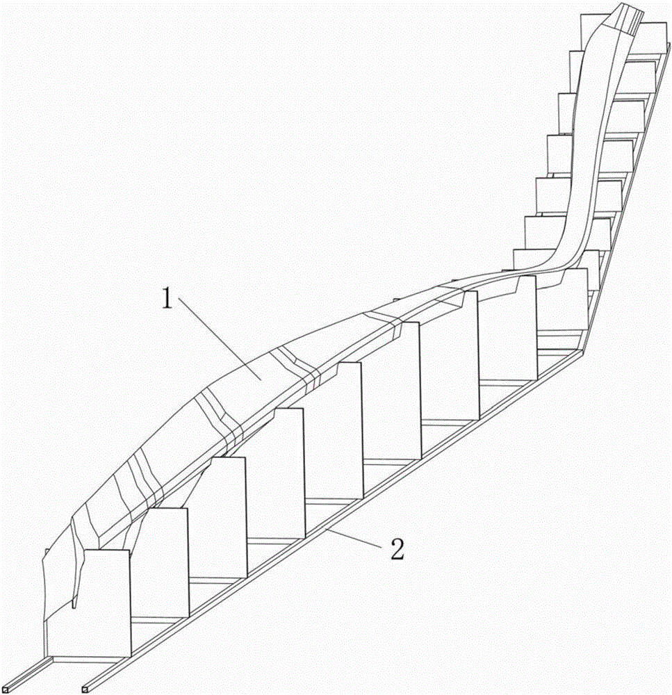
[0026] 1) Make the placement tool 2 for placing the trailing edge UD prefabricated part 1 of the wind power generation blade. After the trailing edge UD prefabricated part 1 is placed on the placement tool 2, its state is consistent with the state in the main form shell layup , in order to facilitate the later parallel transfer, such as figure 1 shown.

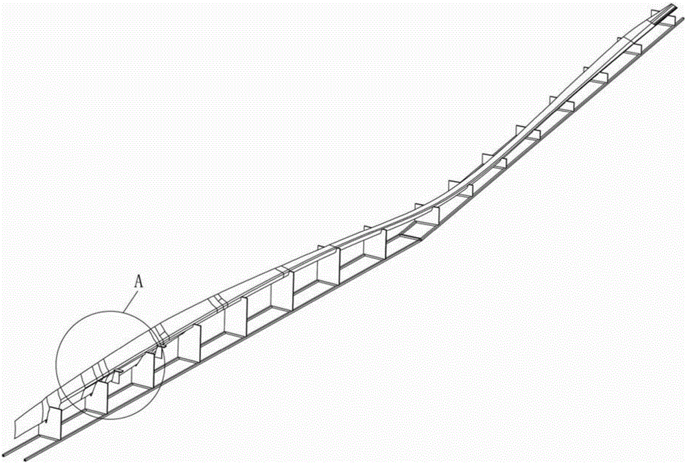
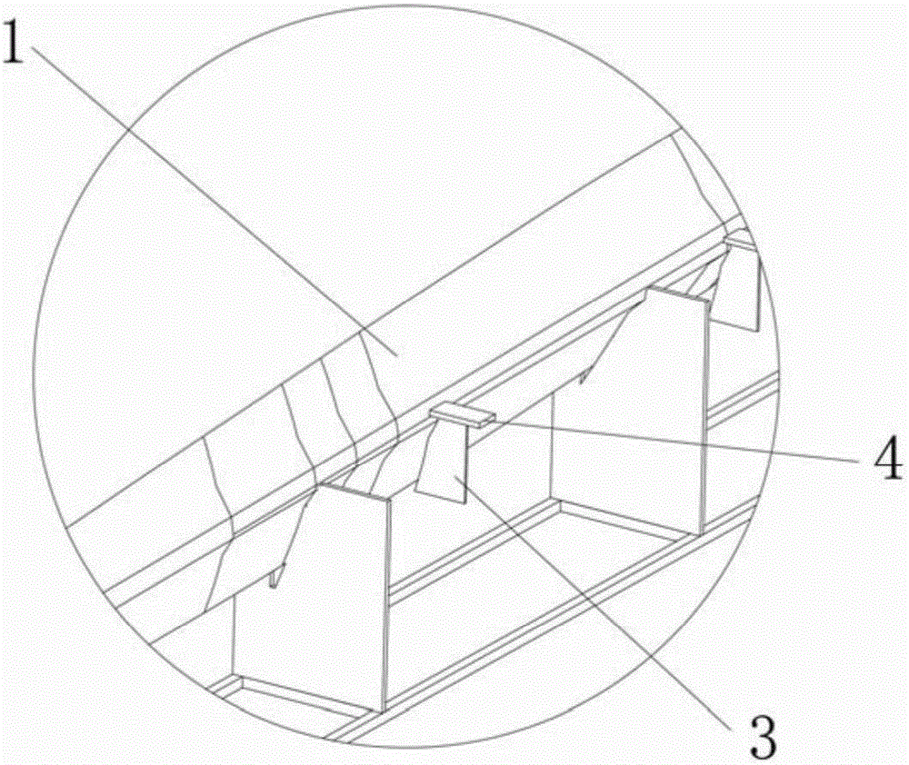
[0027] 2) Find the installation position of the positioning block on the trailing edge UD prefabricated part 1 through the inspection board 3, and install the positioning block 4 after finding it, to solve the positioning problem between the trailing edge UD prefabricated part and the main form shell layer. fixed, such as figure 2 and im...


PUM


Abstract

The invention discloses a method for hanging a wind power generation blade trailing edge UD prefabricated member into a main mold shell body laying layer. The method comprises the steps: firstly, preparing a placing tool of the trailing edge UD prefabricated member, and allowing the state of the trailing edge UD prefabricated member after placement to be consistent with the state in the main mold shell body laying layer; secondly, finding out an installation position of a positioning block on the trailing edge UD prefabricated member through a check plate, and installing the positioning block; followed by preparing a hanging beam, increasing hanging points through the hanging beam, ensuring the state of the trailing edge UD prefabricated member after hanging is not changed relative to the state on the placing tool through selecting a hanging point position, hanging the trailing edge UD prefabricated member stably into the main mold shell body laying layer, and fixing through a fixing tool; and finally, detecting the state of the trailing edge UD prefabricated member in the main mold shell body laying layer by the check plate, and adjusting the state of the trailing edge UD prefabricated member through an adjusting device on the fixing tool, so as to meet requirements. The method can effectively ensure accuracy and reliability of hanging of the wind power generation blade trailing edge UD prefabricated member into the main mold shell body laying layer.

Description

technical field [0001] The invention relates to the technical field of hoisting a UD prefabricated part at the trailing edge of a wind power generation blade into the laying layer of a main formwork shell, in particular to a method for hoisting a UD prefabricated part at the trailing edge of a wind power generating blade into the laying layer of a main formwork shell. Background technique [0002] It is known in the industry that the trailing edge UD of wind power blades is basically made of fixed-width unidirectional glass fiber cloth, which is laid and poured together with the shell. At present, the newly developed 6MW blade, whose trailing edge UD is a whole, has a complicated shape, and cannot be manufactured by the previous method. It needs to be manufactured in advance by prefabricated parts, and it is hoisted into the main mold layer when the shell is laid. When the rear edge UD prefabricated parts are hoisted into the main form shell layer, in order to avoid affectin...

Claims


Application Information

Patent Timeline
Patent Type & Authority Patents(China)
IPC IPC(8): B29C70/30B29C70/54
CPCB29C70/44
Inventor 陈奋威保积佑林雄
Owner 广东明阳新能源材料科技有限公司
Learn More