Automobile exhaust heating device

A heating device, automobile exhaust technology, applied in vehicle parts, transportation and packaging, air treatment equipment, etc., can solve problems such as difficult start, shortened engine life, limited heat, etc., to achieve the effect of increasing temperature and oil bottom temperature

Inactive Publication Date: 2014-08-27
ZHENJIANG COLLEGE
View PDF7 Cites 2 Cited by
  • Summary
  • Abstract
  • Description
  • Claims
  • Application Information

AI Technical Summary

Problems solved by technology

[0002] With the continuous increase of the number of automobiles in our country, automobiles have spread all over the country, and there are footprints of automobiles in towns and villages in various regions. With the increase in the use of automobiles, some problems in the use of automobiles are also constantly reflected, such as The problem of car warmth in winter is particularly prominent, especially in Northeast China, where the average winter temperature is about minus 30°C. When the car is driven at minus 30°C, the temperature of the cab is low. Drivers and passengers feel uncomfortable in this environment for a long time. It is very cold, the driver’s body will be stiff when driving in this environment for a long time, the operation will be inflexible, and traffic accidents will easily occur. Viscous, difficult to start, due to thick oil and poor lubrication, it will accelerate the wear of the engine cylinder and shorten the service life of the engine. Based on the above reasons, car heating devices and engine heating pots are used, but the current heating devices are generally The cooling water of the engine body is used as the heat source. When the car is in a low-temperature environment, the cooling water temperature of the engine is low and the heat provided is limited, and the heating pot usually uses gasoline to heat the engine. This method is not energy-saving enough. Some heating devices that use automobile exhaust as cab heating have complex structures and single functions

Method used


Image

  • Automobile exhaust heating device
  • Automobile exhaust heating device
  • Automobile exhaust heating device

Examples


Embodiment Construction

[0016] The present invention will be further described in detail below in conjunction with the accompanying drawings and embodiments.

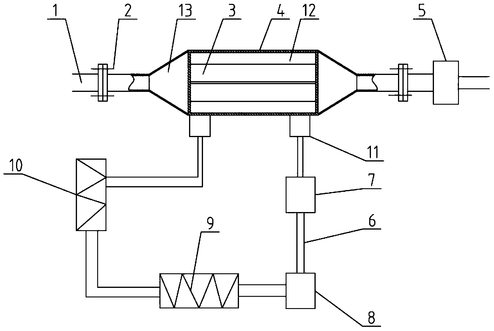
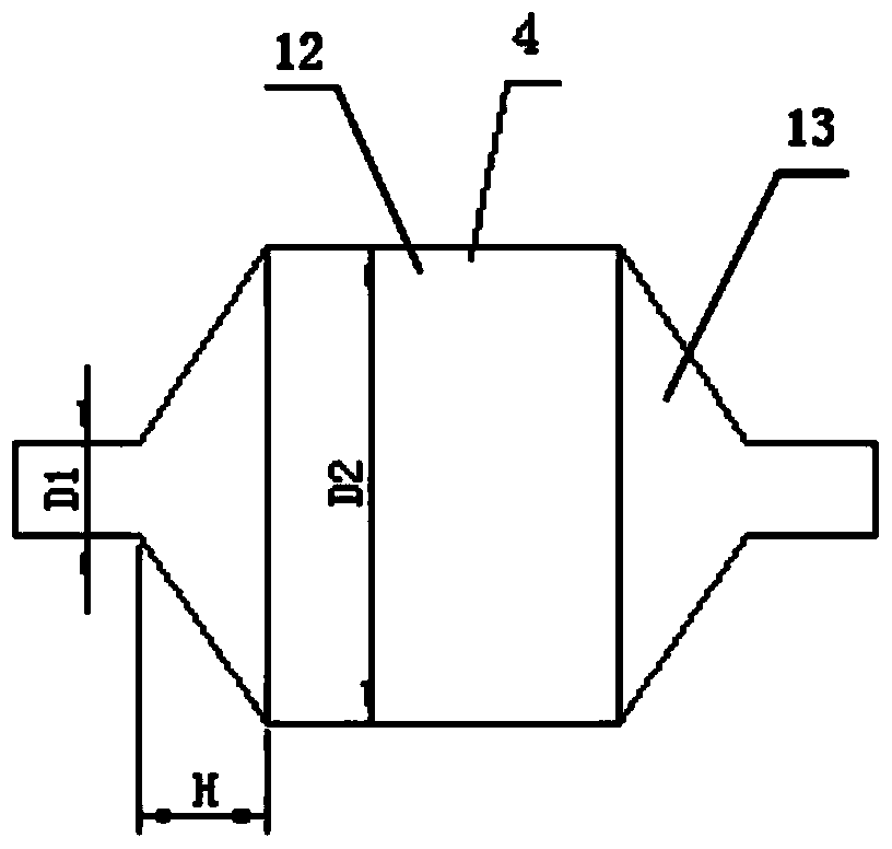
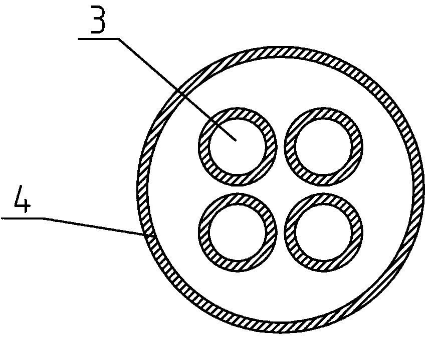
[0017] Such as figure 1 Shown, a kind of automobile exhaust heating device, comprises engine exhaust pipe 1 and muffler 5, also comprises the heat exchanger 4 that communicates described engine exhaust pipe 1 and described muffler 5, and described heat exchanger 4 comprises A porous, hollow and airtight middle part 12 and two trumpet-shaped connecting parts 13 arranged at the inlet end to connect the engine exhaust pipe 1 and connected to the muffler 5 at the outlet end, the holes of the middle part 12 are The inner exhaust pipe 3 communicating with the engine exhaust pipe 1 and the muffler 5 is provided with cooling liquid between the inner exhaust pipe 3 and the heat exchanger 4 housing, and the cooling liquid is from The water outlet of the heat exchanger 4 enters the engine oil pan heater 9 and the radiator 10 through the water pump 7 and...


PUM


Abstract

The invention discloses an automobile exhaust heating device. The automobile exhaust heating device comprises an engine exhaust pipe, a silencer and a heat exchanger, the heat exchanger comprises a porous hollow sealed middle part and two loudspeaker-shaped connecting parts, holes of the middle part are an inner exhaust pipe communicated with the engine exhaust pipe and the silencer, the heat exchanger is filled with cooling liquid, the cooling liquid passes a water pump and a valve in sequence from the water outlet of the heat exchanger to enter an engine oil sump heater and a radiator, and then the cooling liquid flows back to the heat exchanger through the water return hole of the heat exchanger to form a circulating loop. According to the automobile exhaust heating device, the cooling liquid is heated through the high-temperature engine exhaust through the heat exchanger, the cooling liquid is circulated through the water pump, and the heat is supplied to the automobile cab and the automobile engine oil sump for improving the cab temperature through the radiator; the automobile exhaust heating device is capable of improving the engine oil sump temperature and is good for starting and lubricating the engine in winter, in summer, the automobile exhaust heating device can be turned off to restore the normal working system of the automobile.

Description

technical field [0001] The invention relates to a device for recovering and utilizing the heat of automobile exhaust, in particular to a heating device for automobile engine exhaust, which belongs to the technical field of automobiles. Background technique [0002] With the continuous increase of the number of automobiles in our country, automobiles have spread all over the country, and there are footprints of automobiles in towns and villages in various regions. With the increase in the use of automobiles, some problems in the use of automobiles are also constantly reflected, such as The problem of car warmth in winter is particularly prominent, especially in Northeast China, where the average winter temperature is about minus 30°C. When the car is driven at minus 30°C, the temperature of the cab is low. Drivers and passengers feel uncomfortable in this environment for a long time. It is very cold, the driver’s body will be stiff when driving in this environment for a long ...

Claims


Application Information

Patent Timeline
Patent Type & Authority Applications(China)
IPC IPC(8): B60H1/20F01M5/02
Inventor 周炳强刘波翟云峰黄晓艳
Owner ZHENJIANG COLLEGE
Why Eureka
Try Eureka