Liftably-slantwise conveying mechanism

A technology of conveying mechanism and turbine, which is applied in the field of parts conveying, can solve problems such as inclined positioning, and achieve the effect of accurate inclined positioning and accurate inclined angle

Active Publication Date: 2014-08-27
安徽立光电子材料股份有限公司
View PDF6 Cites 1 Cited by
  • Summary
  • Abstract
  • Description
  • Claims
  • Application Information

AI Technical Summary

Problems solved by technology

[0006] The technical problem solved by the invention: on the premise of realizing the vertical conveying

Method used


Image

  • Liftably-slantwise conveying mechanism
  • Liftably-slantwise conveying mechanism
  • Liftably-slantwise conveying mechanism

Examples


Embodiment Construction

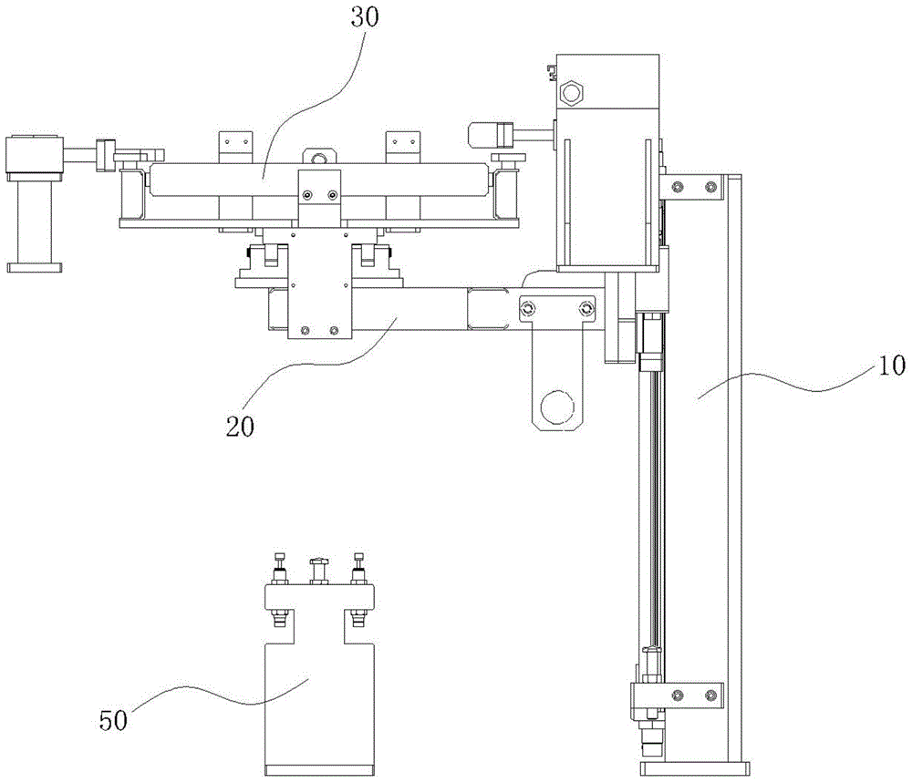
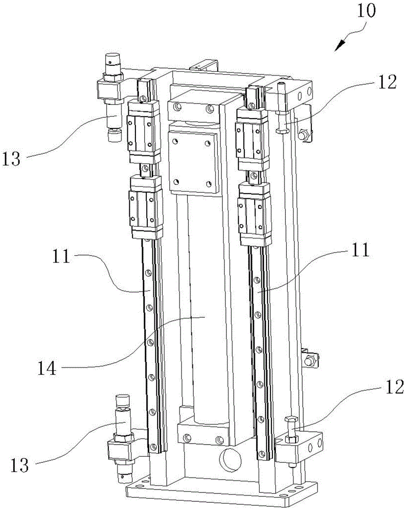
[0028] Such as Figure 1 to Figure 5 As shown, a transport mechanism capable of lifting and tilting includes a support 10 equipped with a cylinder 14, and a lifting platform 20 is installed on the support 10. The support 10 includes a linear guide rail 11, and the linear guide rail 11 is vertically installed on the On both sides of the vertical direction of the support 10, positioning screws 12 and buffers 13 are installed at the upper and lower ends of the linear guide rail 11, and the lifting platform 20 performs lifting action along the linear guide rail 11, and is positioned between the positioning screws 12 and the buffer. 13 actions within a limited range.

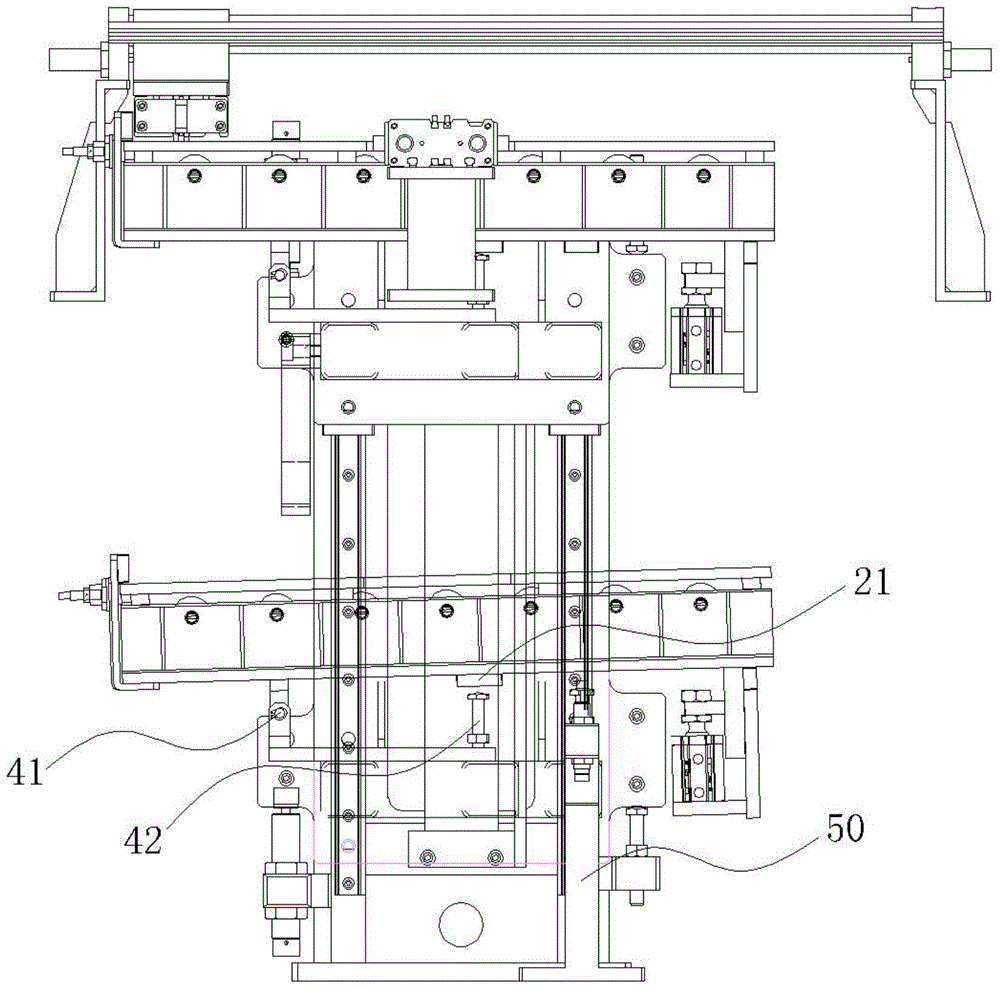
[0029] A roller frame 30 is installed on the lifting frame 20, and the roller frame 30 is connected with the lifting frame 20 through a hinge 41 and a set screw 42, and the hinge 41 and the set screw 42 are respectively located near the two ends below the roller frame 30. , the positioning screw 42 is installed on t...


PUM


Abstract

The invention discloses a liftably-slantwise conveying mechanism. The liftably-slantwise conveying mechanism comprises a support (10) provided with a drive device, a liftable lifting stand (20) installed on the support (10), and a rolling wheel rack (30) installed on the liftable lifting stand (20), wherein the rolling wheel rack (30) is connected with the liftable lifting stand (20) by virtue of a hinge (41) and a location screw (42); the hinge (41) and the location screw (42) are located close to the both ends below the rolling wheel rack (30) respectively; the location screw (42) is installed on the liftable lifting stand (20). The liftably-slantwise conveying mechanism further comprises a stop block (50) installed below one end of the rolling wheel rack (30), and the stop block (50) is located below the location screw (42). By virtue of the technical scheme, the problem of slantwise location for a component during a vertical conveying process is solved on the premise of realizing vertical conveying for the component.

Description

technical field [0001] The invention relates to the field of conveying parts, in particular to a conveying mechanism capable of lifting and tilting. Background technique [0002] Traditional parts conveying devices include belt conveying and track conveying. Among them, belt conveying transports materials in a friction-driven manner, mainly for conveying loose and broken materials, and also for conveying finished parts in some occasions. It has a wide range of applications. However, there are many disadvantages in belt conveying, such as the conveying belt is easy to run off, the items in the conveying process are prone to slipping problems, and the accurate transmission ratio cannot be maintained. In addition, when the belt or track is used to transport the target position of the parts to be transported is fixed, it is impossible to meet the requirements for long-distance and arbitrary position transport of the parts. [0003] With the popularization of automation and semi...

Claims


Application Information

Patent Timeline
IPC IPC(8): B65G21/12
Inventor 张容
Owner 安徽立光电子材料股份有限公司
Why Eureka
Try Eureka