A hoisting device and hoisting method with angle display
A hoisting device and display device technology, which is applied in the directions of transportation and packaging, load hoisting components, etc., can solve the problems of time-consuming, labor-intensive, and inability to install, and achieve the effects of low cost, simple structure, and ensuring work efficiency.
- Summary
- Abstract
- Description
- Claims
- Application Information
AI Technical Summary
Problems solved by technology
Method used
Image
Examples
Embodiment 1
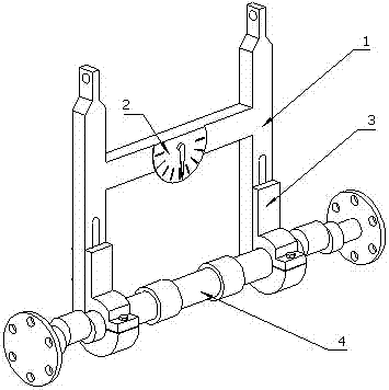
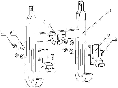
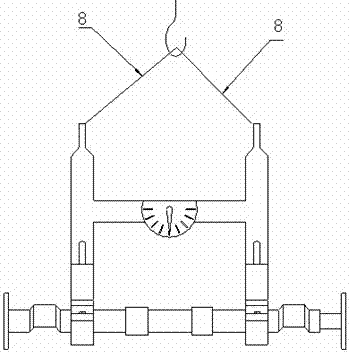
[0031] Such as Figure 1 to Figure 8 The shown lifting device with angle display includes a device lifting device body 1. The lifting device body 1 is an "H" structure, including support structures on both sides and a middle beam. The upper ends of the support structures on both sides are provided with The lifting lugs 101, 102 are provided with an inclination angle display device 2 on the middle beam, and the inclination angle display device 2 includes a semicircular angle dial 201 and a metal pointer 202 arranged thereon.
[0032] The lower ends of the supporting structures on both sides are bent outwards into two hook-shaped structures, and waist-shaped through holes 103 and 104 are arranged on the straight arms at the lower ends of the supporting structures on both sides. 103 and 104 are connected with the hook adjustment slider 3 through the fixing bolts, that is, the upper external thread bolt 301 and the lower external thread bolt 302 in this embodiment. The hook adjust...
Embodiment 2
[0035] Another hoisting device with angle display of the present invention includes a device hoisting device body 10, and the hoisting device body 10 is an "H" structure, including support structures on both sides and a middle beam, and the upper ends of the support structures on both sides are Hanging ears 101 and 102 are provided, and an inclination angle display device 2 is provided on the middle beam, and the inclination angle display device 2 includes a semicircular angle dial 201 and a metal pointer 202 arranged thereon.
[0036] The lower ends of the support structures on both sides protrude outward to form an "L"-shaped supporting plate, and waist-shaped through-holes are arranged on the straight arms at the lower ends of the support structures on both sides, and the waist-shaped through-holes An L-shaped upper plane clamping device 11 is connected to the top by fixing bolts. The vertical side of the L-shaped upper plane clamping device 11 is connected to the waist-shap...
PUM
 Abstract
Description
Claims
Application Information
 - R&D
- Intellectual Property
- Life Sciences
- Materials
- Tech Scout
- Unparalleled Data Quality
- Higher Quality Content
- 60% Fewer Hallucinations
Browse by: Latest US Patents, China's latest patents, Technical Efficacy Thesaurus, Application Domain, Technology Topic, Popular Technical Reports.
© 2025 PatSnap. All rights reserved.Legal|Privacy policy|Modern Slavery Act Transparency Statement|Sitemap|About US| Contact US: help@patsnap.com


