
A rigid cleaning machine

A kind of cleaning machine, rigid technology, applied in general water supply saving, cleaning of open water surface, water conservancy projects, etc., can solve the problems of poor cleaning effect, low insertion force, and inability of grab-type cleaning machine to clean, etc. , to achieve the effect of good cleaning effect, large insertion force, high rigidity and strength

Active Publication Date: 2015-12-09
江苏武东机械有限公司
View PDF6 Cites 0 Cited by
  • Summary
  • Abstract
  • Description
  • Claims
  • Application Information

AI Technical Summary

Problems solved by technology

[0003] The main defect of the grab-type cleaning machine is that the insertion force is determined by the weight of the grab, and the grab is generally not too heavy, so the insertion force is small, especially in the flood season when there is more rain , When flash floods break out and there is a lot of dirt, the cleaning effect is very bad
In addition, when the dirt is straw and inserted vertically into the trash rack or when it freezes in winter, the grab-type cleaning machine basically cannot clean the dirt.

Method used


Image

  • A rigid cleaning machine
  • A rigid cleaning machine
  • A rigid cleaning machine

Examples


Embodiment 1

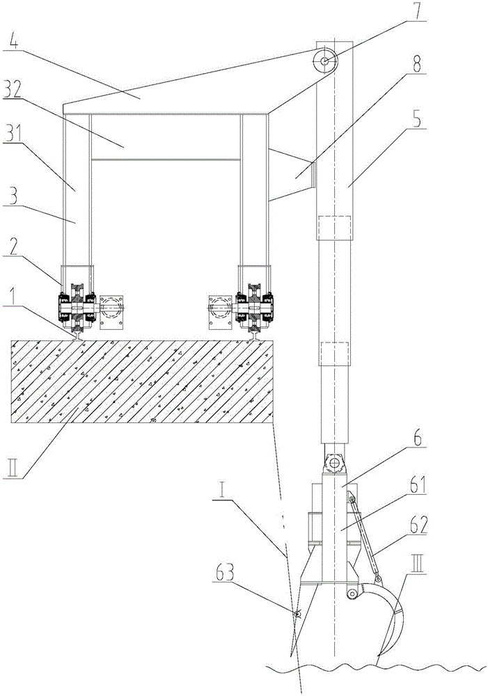
[0021] Such as figure 1 As shown, the trash rack I is located at the bottom side of the foundation II, and there is a certain angle between the trash rack I and the water surface III. 5 is located on the outside of the two uprights 31 in the door frame 3 .

[0022] Since the telescopic sleeve 5 and the grab mechanism 6 are all located on one side of the door frame 3, a rail clamp is provided on the running mechanism 2 walking on the rail 1 to ensure that the door frame 3 on the running mechanism 2 does not fall under the action of external force. overturned.

Embodiment 2

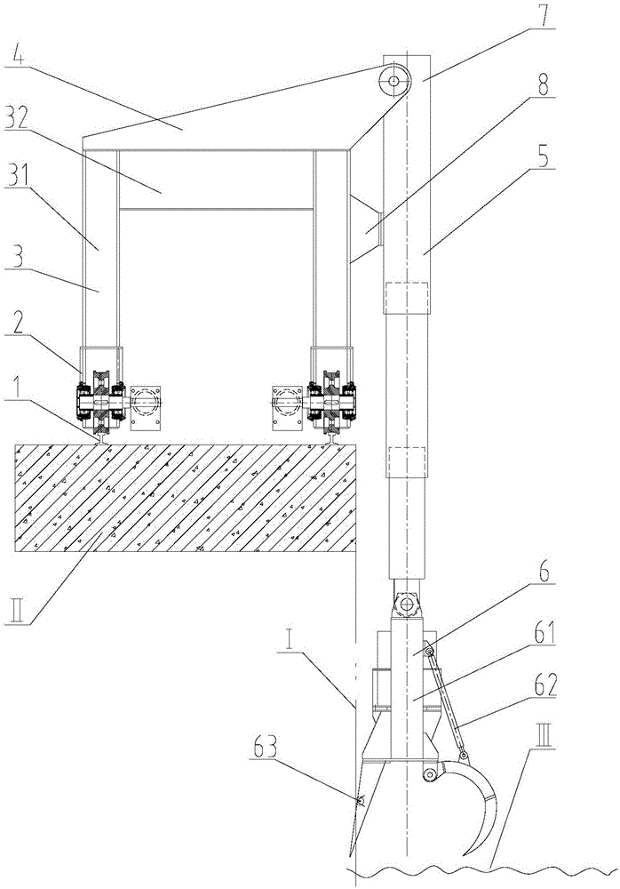
[0024] Such as figure 2 As shown, the trash rack I is located at the bottom side of the foundation II, and is installed vertically between the trash rack I and the water surface III, the fulcrum fixing plate 4 is fixedly connected to the upper surface of the beam 32 in the door frame 3, and the telescopic sleeve 5 is located at the door The outer sides of two columns 31 in the frame 3.

[0025] Since the telescopic sleeve 5 and the grab mechanism 6 are all located on one side of the door frame 3, a rail clamp is provided on the running mechanism 2 walking on the rail 1 to ensure that the door frame 3 on the running mechanism 2 does not fall under the action of external force. overturned.

Embodiment 3

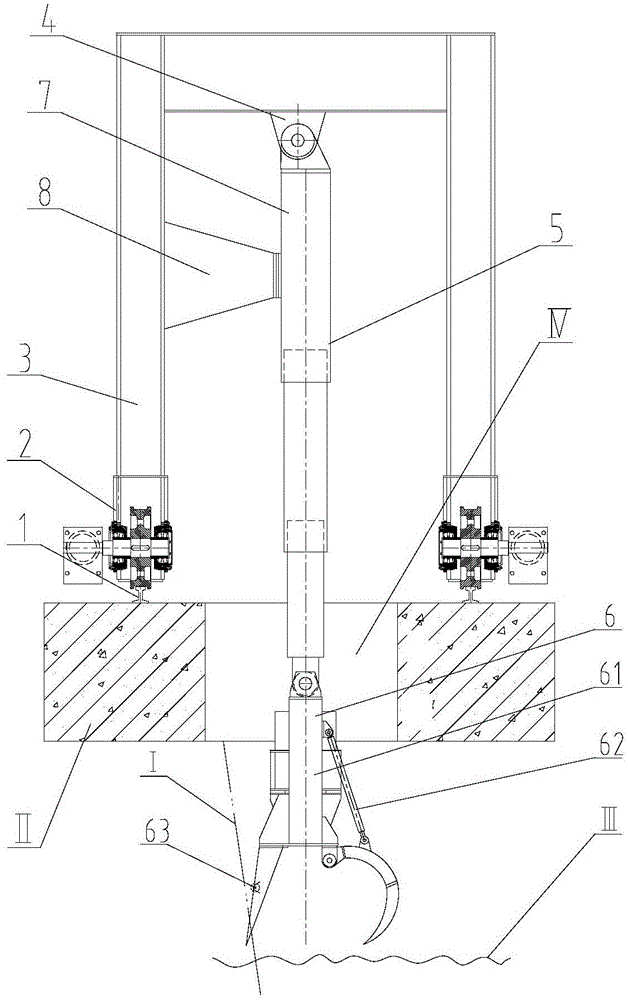
[0027] Such as image 3 As shown, there is a through hole IV through the foundation II, the trash rack I is located at the bottom of the through hole IV in the foundation II, the trash rack I and the water surface III are installed at a certain angle, and the fulcrum fixing plate 4 is fixedly connected On the lower surface of the beam 32 in the door frame 3, the telescopic sleeve 5 is located between the two columns 31 in the door frame 3 and passes through the through hole IV.

[0028] Since the telescopic sleeve 5 and the grab mechanism 6 are all located in the middle of the door frame 3, the door frame 3 on the running gear 2 is not prone to overturning, so a rail clamp can be set on the running gear 2 walking on the rail 1, or not. Set up rail clamps.


PUM


Abstract

The invention relates to the technical field of the water conservancy machinery and in particular relates to a rigid trash remover. The rigid trash remover comprises two rails which are distributed in parallel to a trash rack and fixedly mounted on a base; the trash rack is located at the bottom of the base; traveling mechanisms capable of moving back and forth on the rails are arranged on the two rails, respectively; a portal is arranged on the two traveling mechanisms, a support-point fixed plate is fixedly connected to the portal, and a telescopic sleeve which is perpendicular to the water surface and next to one side of the trash rack is movably connected to the support-point fixed plate; the telescopic sleeve is in the form of a hydraulic oil cylinder; a grab mechanism is fixedly connected to the bottom of the telescopic sleeve and comprises a hydraulic grab; a grab opening / closing oil cylinder is arranged on the hydraulic grab. The rigid trash remover is relatively high in rigidity and strength and relatively high in hydraulic control trash insertion force; the rigid trash remover especially has special trash removing effect on straw trash perpendicular to the trash rack, and meanwhile, is capable of breaking ice.

Description

technical field [0001] The invention relates to the technical field of water conservancy machinery, in particular to a rigid cleaning machine. Background technique [0002] At present, the cleaning machines used in the market mainly have two structural forms: grab type and rotary type. Among them, the grab-type cleaning machines all adopt the following working form: the steel wire rope of the hoisting mechanism is wound on the reel, and the reel is rotated positively and negatively to control the rise or fall of the grab, so as to realize the opening of the bucket to drop and insert the dirt, and the closed bucket to grab the dirt and then rise , The size of the grab's dirt insertion force is only determined by the grab's own weight. [0003] The main defect of the grab-type cleaning machine is that the insertion force is determined by the weight of the grab, and the grab is generally not too heavy, so the insertion force is small, especially in the flood season when there ...

Claims


Application Information

Patent Timeline
Patent Type & Authority Patents(China)
IPC IPC(8): E02B15/10
CPCY02A20/204
Inventor 钟晓东
Owner 江苏武东机械有限公司
Learn More