Vertical cable paying-off device

A technology of pay-off device and cable, which is applied to the installation of cables, the arrangement of cables between relatively moving parts, electrical components, etc. Effort-saving, weight-saving, and stability-enhancing effects

Active Publication Date: 2014-08-27
STATE GRID SICHUAN ELECTRIC POWER
View PDF5 Cites 1 Cited by
  • Summary
  • Abstract
  • Description
  • Claims
  • Application Information

AI Technical Summary

Problems solved by technology

Although this kind of pay-off frame has strong versatility, the cable is very heavy, and it is easy to cause the positioning bolt to break and the slide block to slide down during repeated use, making the connection unstable and prone to construction accidents.
In addition, the beam is directly placed on the slider, which is easy to move, rotate or shake, which affects the use

Method used


Image

  • Vertical cable paying-off device
  • Vertical cable paying-off device
  • Vertical cable paying-off device

Examples


Embodiment 1

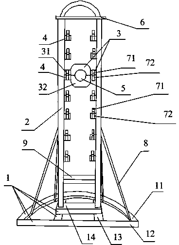
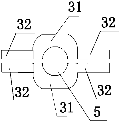
[0026] Such as figure 1 , 2 . As shown in 3, the vertical cable pay-off device includes a base 1, 2 uprights 2 vertically connected to the base 1, a limit plate 6 connected to the upper ends of the 2 uprights 2, and a support is provided between the 2 uprights 2 Mechanism 3, a plurality of fixed blocks 4 are evenly distributed from top to bottom on the two opposite end surfaces of the two columns 2, and the fixed blocks 4 are welded on the columns 2; the support mechanism 3 is composed of two support plates 31 and a support column 32, the support plate 31 is longitudinally arranged, and the center of the support plate 31 is provided with a semicircular groove 5, and one notch of the semicircular groove 5 of the two support plates 31 is set upward, and the other notch is set downward. The semicircular groove 5 constitutes a circular through groove, and the beam for fixing the coil can be fixed in the circular through groove; the two ends of the support plate 31 are respectivel...

Embodiment 2

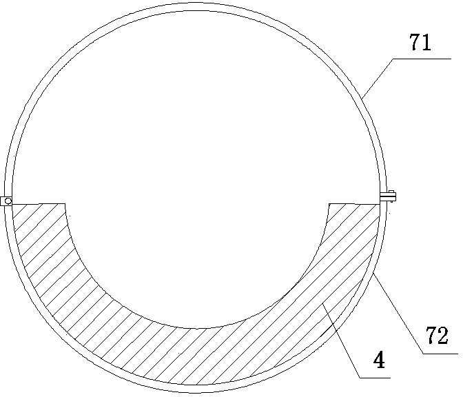
[0029] On the basis of Embodiment 1, the support column 32 of the vertical cable pay-off device in this embodiment is a semi-cylindrical structure; the fixed block 4 is a hollow semi-cylinder, image 3 It is a cross-sectional view of the fixed block. The inner diameter of the semi-cylindrical cylinder is equal to the radius of the support column 32, so the semi-cylindrical support columns 32 at both ends of the support plate 31 located below can just be placed in the fixed block 4 with the plane facing upwards and located at the top The semi-cylindrical support columns 32 at the two ends of the support plate 31 are placed on the plane downwards, and the support columns 32 of the two support plates 31 form a cylinder, the lower half of which is located in the semi-cylindrical fixed block 4, and the upper end passes through the upper The hoop 71 and the lower hoop 72 are fixed.

Embodiment 3

[0031] The difference between this embodiment and Embodiment 2 is that both the support column 32 and the fixed block 4 are rectangular parallelepiped structures, and the second groove on the fixed block 4 is also rectangular parallelepiped. The support columns 32 are the same, and the height is twice as high as the support columns 32, so that the two support columns 32 are conveniently placed in the second groove, and then fixed by two clamps.


PUM


Abstract

The invention discloses a vertical cable paying-off device comprising a base and two stand columns arranged on the base. A supporting mechanism is arranged between the two stand columns. The two opposite end faces of the two stand columns are respectively and evenly provided with a plurality of fixing blocks from top to bottom. The supporting mechanism is composed of two supporting plates and supporting columns connected to the left ends and the right ends of the supporting plates. A semicircular groove is formed in each supporting plate. The semicircular groove of one supporting plate faces upwards and the semicircular groove of the other supporting plate faces downwards. A second groove used for containing the corresponding supporting column is formed in the upper portion of each fixing block. The opening of each second groove faces upwards. Each fixing block is further provided with an upper clamping hoop and a lower clamping hoop, wherein the lower clamping hoop is fixed to the lower end of the fixing block, the upper clamping hoop is located above the corresponding supporting column, and the two ends of the upper clamping hoop are connected with the two ends of the lower clamping hoop. By the adoption of the vertical cable paying-off device, on the premise that the universality of the device is guaranteed, connection of the supporting mechanism is more stable, and a cross beam used for fixing a cable reel is prevented from moving. The vertical cable paying-off device has the advantages of being simple and compact in structure, convenient to use, low in cost and the like.

Description

technical field [0001] The invention relates to the field of electric power construction auxiliary equipment, in particular to a vertical cable pay-off device. Background technique [0002] The cables in the prior art are coiled on the cable rack, and a coil of cables often weighs several hundred catties or even a few tons. In the process of traditional engineering construction, the entire coil of cables is often placed on the ground, and a special person is responsible for placing the cables Disassembled from the cable rack for laying for laying and dismantling. Therefore, a pay-off frame is generally used to pay off the cables. [0003] The large-scale pay-off frame is generally higher, and it is very difficult to directly put the winding reel on the pay-off frame, so it is often used to set the pay-off reel on a beam first, and then fix the beam to the pay-off frame. In order to enhance the versatility of the pay-off frame, the height of the beam can be set according to...

Claims


Application Information

Patent Timeline
Patent Type & Authority Applications(China)
IPC IPC(8): H02G11/00
Inventor 方玉
Owner STATE GRID SICHUAN ELECTRIC POWER
Why Eureka
Try Eureka