Headless compression screw with integrated reduction-compression instrument

a compression screw and compression screw technology, applied in the field of bone screws, can solve problems such as screw head recurrence, and achieve the effect of high connection stability

Active Publication Date: 2012-07-10
SYNTHES GMBH
View PDF15 Cites 28 Cited by
  • Summary
  • Abstract
  • Description
  • Claims
  • Application Information

AI Technical Summary

Benefits of technology

[0007]An advantage of the inventive bone screw and the inventive device are that due to the pitch of the external thread at the front threaded segment and at the rear threaded segment being the same, the steps of setting the bone fragments, compressing the bone fragments, and recessing the head of the screw can be carried out separately and in a controlled manner.
[0008]Because the rear threaded segment is configured with a core diameter, which may be larger than or equal to the external diameter of the front threaded segment, interaction of the rear threaded segment with the thread already cut in the bone fragments for the front threaded segment can be avoided.
[0010]A preferred embodiment of the inventive bone screw includes, between the two threaded segments, a middle, threadless segment, which has an external diameter, which is smaller than or equal to the core diameter of the external thread at the front threaded segment. With that, the front threaded segment can be screwed completely into the distal bone fragment and the borehole in the proximal bone fragment does not have to be enlarged relative to the borehole in the distal bone fragment for setting and compressing the bone fragments. Compared to embodiments of known bone screws, the front threaded segment of which directly adjoins the rear threaded segment in the axial direction and for which the borehole in the proximal bone fragment would have to be enlarged so that the front threaded segment can be screwed only into the distal bone fragment, a higher stability of the connection between the bone screw and the proximal bone fragment can furthermore be attained with the present device.
[0011]The inventive device serves for setting, compressing and fixing bone fragments by means of a bone screw and includes a surgical implantation instrument, which has a central borehole through which a screwdriver can be passed, extending coaxially through the implantation instrument. Furthermore, the central borehole is expanded from the front end of the implantation instrument up to a depth T, so that a shoulder is formed at the depth T. In the expanded part of the central borehole, there is an internal thread, which is complementary to the external thread of the rear threaded segment of the bone screw, so that the rear threaded segment of the bone screw can be screwed into the central borehole up to a depth T. The depth T is selected so that T may be greater than L, where L is the length of the rear threaded segment of the bone screw. With that, it can be achieved that the rear threaded segment of the bone screw can be screwed completely into the central borehole of the implantation instrument. However, T may also be equal to or less than L, which may have the effect of partially inserting the rear threaded segment of the bone screw into the central borehole.

Problems solved by technology

It may be a disadvantage of this particular construction of bone screws that the two external threads have different pitches, so that the different steps for the implantation, the setting the bone fragments, the compression of the bone fragments and the recessing of the screw head cannot be carried out separately from one another.

Method used


Image

  • Headless compression screw with integrated reduction-compression instrument
  • Headless compression screw with integrated reduction-compression instrument
  • Headless compression screw with integrated reduction-compression instrument

Examples


Embodiment Construction

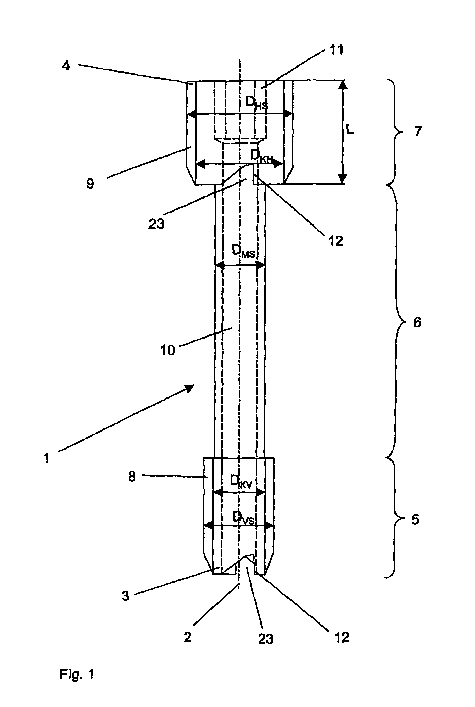
[0044]A preferred embodiment of the inventive bone screw 1 is shown in FIG. 1. This bone screw 1 includes a rear threaded segment 7 with an external thread 9, which has a core diameter DKH, an external diameter DHS and a pitch SH, a middle, threadless segment 6 with an external diameter DMS, which adjoins the rear threaded segment 7 coaxially with the longitudinal axis 2, and a front threaded segment 5 with an external thread 8, which has a core diameter DKV, an external diameter DVS and a pitch SV. The two threaded segments 5, 7 have different diameters, that is, the core diameter DKH of the rear threaded segment 7 is larger than or equal to the external diameter DVS of the front threaded segment 5. The pitches of the two external threads 8, 9 may be identical, or may be different from one another. Moreover, the lead of the front threaded segment 5 may be equal to or different from the lead of the rear threaded segment 7. The external diameter DMS of the middle segment 6 is smaller...


PUM


Abstract

A bone screw is provided having first and second threaded portions of different diameter separated by a middle portion that is unthreaded so that the bone screw may be inserted into a pair of adjacent bone fragments and used to compress the fragments together by driving the screw into a hole drilled in the fragments. An installation tool is also disclosed for threadably engaging one end of the bone screw and is used to initially drive the screw into the bone hole. Thereafter, a screwdriver may be inserted through the tool and into engagement with a recess in the bone screw and may be used to drive the screw fully into the bone and to separate the bone screw from the installation tool. A method of installation is further provided.

Description

CROSS REFERENCE TO RELATED APPLICATION[0001]This application is a continuation-in-part of U.S. patent application Ser. No. 10 / 861,818 to Frenk et al, filed Jun. 4, 2004, which is a continuation of International Application No. PCT / CH01 / 00698 to Frenk et al., filed Dec. 4, 2001, the entirety of both applications is hereby incorporated by reference thereto.FIELD OF THE INVENTION[0002]The invention relates to a bone screw for connecting two bone fragments, to a device for implanting such a bone screw, and to a method for setting, compressing and / or fixing bone fragments.BACKGROUND OF THE INVENTION[0003]Bone screws are used in various ways in osteosynthesis, for example, for setting bone fragments, as compression screws or for fixing bone fragments.[0004]A bone screw with two axially terminal threaded segments and a middle threadless segment is known from U.S. Pat. No. 5,019,079 to Ross. The diameter of the middle segment corresponds essentially to the external diameter of the external ...

Claims


Application Information

Patent Timeline
Patent Type & Authority Patents(United States)
IPC IPC(8): A61B17/58A61B17/86A61B17/88
CPCA61B17/863A61B17/8875A61B17/8886A61B17/861A61B2017/0046A61B17/864A61B17/56A61B17/58A61B17/86A61B17/88
Inventor YEVMENENKO, YANPISTOIA, WALTERFRENK, ANDREBEUTTER, FLORIANCICOIRA, FRANCO
Owner SYNTHES GMBH
Why Eureka
Try Eureka