Mini skirt aerodynamic fairing device for reducing the aerodynamic drag of ground vehicles

a technology of aerodynamic fairing and mini skirt, which is applied in the direction of roofs, vehicle arrangements, transportation and packaging, etc., can solve the problems of limited effectiveness of these devices, unsteady and dynamic undercarriage flow, and unsteady undercarriage flow, so as to enhance the flow blocking performance of each of the two structures

Inactive Publication Date: 2010-06-22
WOOD RICHARD
View PDF138 Cites 79 Cited by
  • Summary
  • Abstract
  • Description
  • Claims
  • Application Information

AI Technical Summary

Benefits of technology

[0011]One aspect of the invention is to prohibit flow from entering the trailer undercarriage region and interacting with the complex geometry comprising the trailer undercarriage and wheel assembly by creating two similar structures that attach to the trailer underside near the two outside edges of the trailer. The two similar structures comprising the present invention are light-weight aerodynamic fairings that attach to the undercarriage of a dry van, refer, flat deck, or tanker trailer near the two outside edges of the trailer. The two similar structures are of minimum vertical extent and include two vertically aligned surfaces and one horizontal surface that attach to the underside of the trailer near the trailer outside edge. The outer edge of each structure is positioned parallel to and below each outer side edge of the trailer. Each structure extends as close as practical to the ground based upon operational and maintenance criteria. Each structure is located longitudinally between the trailer wheel assembly and the tractor aft wheel set. Each structure is variable in length and is capable of covering a variable longitudinal distance between the trailer wheel assembly and the tractor rear wheels.
[0012]The flow blocking performance of each of the two structures is enhanced through the effective use of three flow control concepts: vortex generation, upwash management, and ground effect interference. Each of the two structures accomplishes the flow control and drag reduction goals with two vertically orientated surfaces and one horizontal surface. The two vertically orientated surfaces are an outer vertical surface located at the outside edge of the trailer and an inner vertical surface located inboard of the first surface. The horizontal surface extends between the two upper edges of the two vertical surfaces to create an inverted “U” shaped channel. The two vertical surfaces of each structure are of equivalent longitudinal and vertical length and the lower edge of both surfaces is aerodynamically sharp.
[0014]The outer vertical surface of the structure is designed to both block flow from entering the undercarriage region and to turn the flow passing under the outer vertical surface upward thereby creating an upwash field between the two vertical surfaces. The upwash field is generated by means of a coherent vortex structure emanating from the aerodynamically sharp lower edge of the outer surface. The inner vertical surface blocks the upwash field from flowing inboard and interacting with the trailer undercarriage and wheel assembly. The horizontal surface blocks the upwash flow from interacting with the trailer undercarriage in the region between the two vertical surfaces. The result of the flow control techniques allows the present invention to block a significantly greater mass of flow from entering the undercarriage region compared to a fairing with a single vertical surface of equal vertical extent. The addition of a horizontal surface between the two vertical surfaces ensures that the blocked upwash flow does not generate a drag force. The invention also takes advantage of the increased turbulence in the flow adjacent to the road surface at the side edge of the trailer to further promote upwash thereby increasing the effective blocking area of the structure. Although upwash is present for all existing trailer undercarriage flow blocking fairings, the present invention is the only device that captures the upwash field and thereby controls a greater mass of air from entering the undercarriage region by means of the inner vertical surface and ensues that the blocked and captured flow does not generate a drag by means of the horizontal surface. The ability of the present invention to block a greater mass of flow with less vertical extent from the trailer undercarriage, compared to existing single surface fairings, allows the present invention to provide a larger vertical gap between the ground or road surface and the invention lower edge, thereby eliminating the need for vertically movable, deflectable, and actuated surfaces to adapt to various surface and / or road structures that may impact the lower edge of the fairing. It also results in a reduced aerodynamic load on the vertical surfaces that eliminates the need for structural bracing and supports, thereby reducing or eliminating device drag. Components of the invention may be smooth and aligned parallel with the vehicle axis, thereby eliminating device associated pressure drag.

Problems solved by technology

The undercarriage flow of a trailer is characterized as unsteady and dynamic and comprised of various size and strength eddy currents.
The unsteady nature of the undercarriage flow is a result of the flow interacting with the ground or road, rotating wheels, brake systems, axels, tractor undercarriage flow, and the various components comprising the trailer lower surface.
The limited effectiveness of these devices is a result of the drag generated by the device, referred to as device drag.
These devices only reduce the wheel assembly drag and do not reduce the remaining undercarriage drag associated with the various trailer components.
These representative flow blocking devices, while successful in reducing the mass of flow entering the trailer undercarriage region are either simple rigid structures or they are complex active, flexible and variable geometry systems.
Limiting the vertical and longitudinal extent of the device significantly reduces the flow blocking capability and results in a minimal aerodynamic drag reduction benefit.
The complex devices typically consist of multiple components.
The complexity of these devices results in increased weight, maintenance, and cost.
These support and bracing structures also collect debris, snow and ice during operation resulting in an increase in maintenance and repair requirements.

Method used


Image

  • Mini skirt aerodynamic fairing device for reducing the aerodynamic drag of ground vehicles
  • Mini skirt aerodynamic fairing device for reducing the aerodynamic drag of ground vehicles
  • Mini skirt aerodynamic fairing device for reducing the aerodynamic drag of ground vehicles

Examples


Embodiment Construction

[0041]The following descriptions are of exemplary embodiments of the invention only, and are not intended to limit the scope, applicability or configuration of the invention in any way. Rather the following description is intended to provide a convenient illustration for implementing various embodiments of the invention. As will become apparent, various changes may be made in the function and arrangement of the elements described herein without departing from the spirit and scope of the invention. For example, though not specifically described, many shapes, widths, leading edge shapes, spacing and orientation of the forward extended plurality of panels, candidate vehicles that can benefit from the device, fabrication means and material, attachments means and material should be understood to fall within the scope of the present invention.

[0042]Referring now in detail to the drawings, like numerals herein designate like numbered parts in the figures.

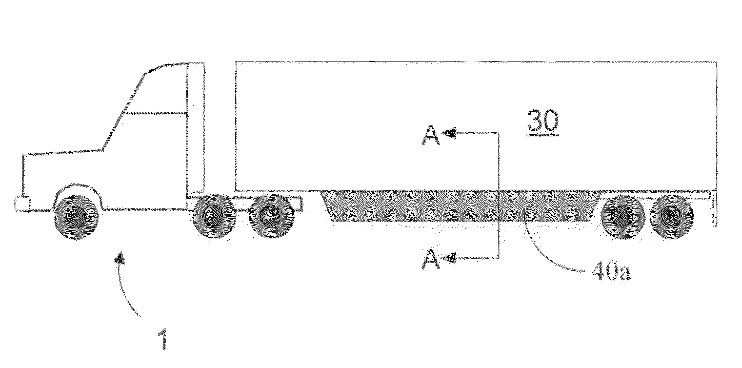
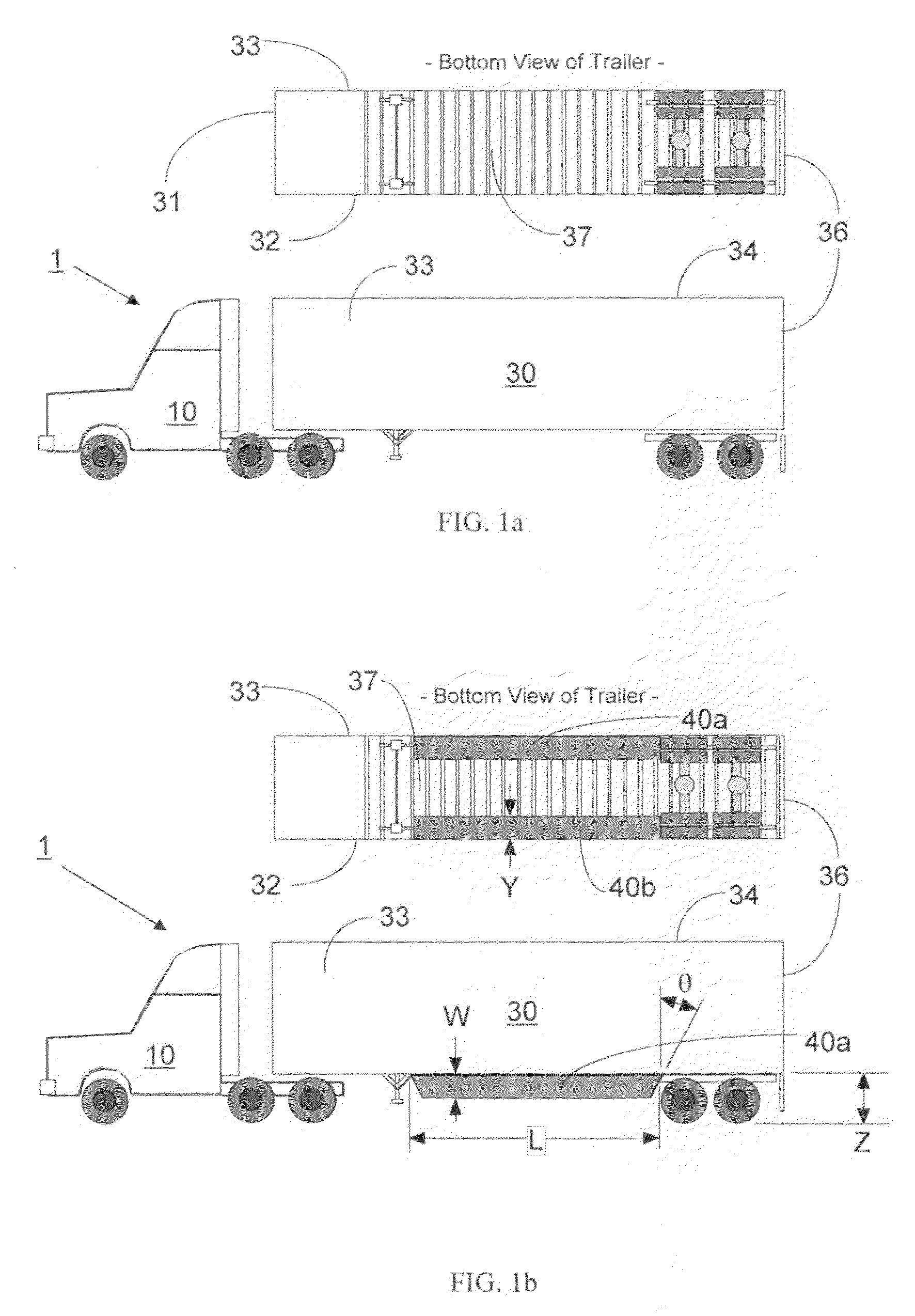
[0043]FIG. 1 shows a typical ground...


PUM


Abstract

A device for the reduction of aerodynamic drag and for improved performance and stability of ground vehicles by reducing the mass and velocity of the flow passing under a vehicle is described. The device is particularly suited for a tractor-trailer truck system that includes a motorized lead vehicle pulling one or more non-motorized vehicles. The device is designed to control the flow from entering the undercarriage region from the side of a trailer of a tractor-trailer truck system.

Description

CROSS-REFERENCE TO RELATED APPLICATION[0001]This application is a continuation-in-part of prior application U.S. application Ser. No. 11 / 811,541 titled “Mini Skirt Aerodynamic Fairing Device for Reducing the Aerodynamic Drag of Group Vehicles,” filed on Jun. 11, 2007, now U.S. Pat. No. 7,497,502 which claimed the benefit of U.S. Provisional Application No. 60 / 814,303, filed Jun. 19, 2006, the entire contents of both of which are incorporated herein by reference.ORIGIN OF THE INVENTION[0002]The invention described herein was made by employees of the United States Government, and may be manufactured and used by or for the Government without payment of any royalties thereon or therefore.FIELD OF INVENTION[0003]The invention relates to the reduction of aerodynamic drag for moving ground vehicles; specifically to an improved method and device for the reduction of aerodynamic drag and for improved performance and stability of ground vehicles by reducing the mass and velocity of the flow p...

Claims


Application Information

Patent Timeline
Patent Type & Authority Patents(United States)
IPC IPC(8): B60J7/00
CPCB62D35/001
Inventor WOOD, RICHARD
Owner WOOD RICHARD
Why Eureka
Try Eureka