3D printing method and device for parts with large inclination angle, and electronically controlled multifunctional powder separator

A tilting angle and 3D printing technology, which is applied in the field of 3D printing methods and devices for metal parts, can solve problems such as powder sticking, complicated process, nodules, etc., and achieve the effect of eliminating molten pool flow and increasing the limit tilt angle

Inactive Publication Date: 2017-01-18
XI'AN INST OF OPTICS & FINE MECHANICS - CHINESE ACAD OF SCI
View PDF6 Cites 0 Cited by
  • Summary
  • Abstract
  • Description
  • Claims
  • Application Information

AI Technical Summary

Problems solved by technology

[0003] The purpose of the present invention is to provide a 3D printing process and device that can form parts with a large inclination angle without support, which solves the problems of nodules and powder sticking in the existing 3D printing process and devices for forming parts with a large inclination angle Phenomenon, technical problems of complicated process and deformation of parts

Method used


Image

  • 3D printing method and device for parts with large inclination angle, and electronically controlled multifunctional powder separator
  • 3D printing method and device for parts with large inclination angle, and electronically controlled multifunctional powder separator

Examples


Embodiment Construction

[0039] The forming process is as follows:

[0040] (1) Part area division:

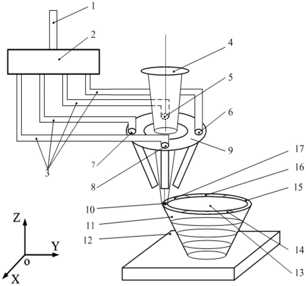
[0041] Firstly, the part is divided into part internal area 13 , part front boundary 14 , part front right boundary 15 , part rear boundary 16 , and part left boundary 17 .

[0042] (2) The corresponding nozzle is determined when different regions are formed:

[0043] When forming the internal area 13 of the part, the powder in the powder feeding pipe 1 is divided into 4 parts by the electronically controlled multifunctional powder separator 2, and the powder is sprayed by 4 nozzles (5, 6, 7, 8) at the same time. The powder feeding amount in each nozzle is 1 / 4 of the powder feeding amount of the main powder feeding pipe;

[0044] When the left boundary of the forming part is 17, all the powder in the powder feeding pipe 1 is sent to the left powder feeding pipe 7 through the electronically controlled multifunctional powder separator 2, and the powder is sent from the left powder feeding pipe 7 to th...


PUM


Abstract

The invention provides a 3D printing method and device of a large-inclination part and an electronic control multifunctional powder distribution device. The printing method includes the steps of part region division, corresponding spray tube determining when different border regions are formed and part forming. When the interior region of the part is formed, the electronic control multifunctional powder distribution device equally divides the powder in a power feeding tube and powder spraying is conducted by multiple spray tubes; when any border of the border region of the part is formed, the electronic control multifunctional powder distribution device conveys all the powder in the powder feeding tube to the corresponding spray tubes of the border, and the corresponding spray tubes convey the powder to a molten bath. By means of the 3D printing method and device of the large-inclination part, the spray tubes at the different positions of multi-tube coaxial nozzles are used for spraying the powder separately when the borders of the inclined part are formed, the force direction of the molten bath is changed, flow phenomenon of the powder in the molten bath caused by the gravity and the powder impact force when the borders of the inclined part are formed is reduced even is eliminated, and the limit of the inclined angle of the formed part can be finally increased without adding support conditions.

Description

technical field [0001] The present invention relates to a 3D printing method and device for metal parts, in particular to a 3D printing process and device for forming parts with a large inclination angle without support. The present invention also relates to a 3D printing powder separating device. Background technique [0002] 3D printing technology can form a variety of complex structural parts by layering layers of materials. Usually, when forming parts with too large inclination angle, the molten pool will flow due to gravity and powder impact force, resulting in nodules and nodules on the surface of the parts. Powder sticking phenomenon, and the maximum inclination angle that can be formed by the current method of coaxial powder feeding is limited. Therefore, it is often necessary to add supports when forming parts with a large inclination and local parts of the parts. However, removing the supports after the parts are formed will complicate the process, and even some pa...

Claims


Application Information

Patent Timeline
Patent Type & Authority Patents(China)
IPC IPC(8): B22F3/105
Inventor 贺斌杨小君赵卫李睿江浩
Owner XI'AN INST OF OPTICS & FINE MECHANICS - CHINESE ACAD OF SCI
Why Eureka
Try Eureka