
TBCC air inlet adjusting mechanism design method based on electric sliding door principle

A design method and a technology for adjusting mechanisms, which are applied to mechanical equipment, jet propulsion devices, gas turbine devices, etc., can solve problems such as large torque and blocking the airflow of bronchial vents, so as to improve sports performance and efficiency and reduce negative effects , Improve the effect of airtight characteristics

Pending Publication Date: 2021-05-25
XIAMEN UNIV
View PDF6 Cites 1 Cited by
  • Summary
  • Abstract
  • Description
  • Claims
  • Application Information

AI Technical Summary

Problems solved by technology

[0006] The main purpose of the present invention is to overcome the defects in the prior art, to provide a solution based on the rotation of the veneer around the central axis to adjust the area of ​​the bronchial ventilator, the problem that the required torque is too large, and to solve the problem that the blades are opened based on the principle of the blinds. At the same time, the shaft still has the problem of blocking the bronchial vents and causing many negative effects on the airflow. It is convenient to control and realize continuous adjustment of the bronchial ventilation area during the opening and closing process, start and stop at any time, and open and close. A completely airtight design method of TBCC air intake adjustment mechanism based on the principle of electric sliding doors

Method used


Image

  • TBCC air inlet adjusting mechanism design method based on electric sliding door principle
  • TBCC air inlet adjusting mechanism design method based on electric sliding door principle
  • TBCC air inlet adjusting mechanism design method based on electric sliding door principle

Examples


Embodiment Construction

[0024]The invention is further described below with reference to the specific embodiments.

[0025]The present invention provides a TBCC inlet adjustment mechanism based on electric push-pull door principles, in order to make the invention, the embodiments of the present invention will be described in detail. It should be understood that the specific examples described herein are intended to explain the present invention, but is not intended to limit the invention.

[0026]The invention includes the following steps:

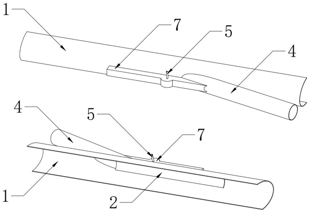
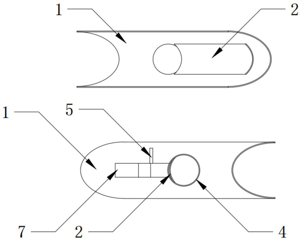
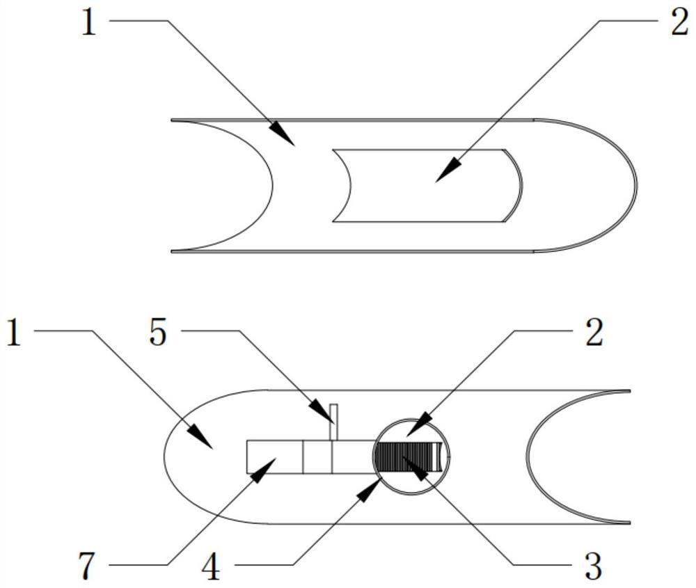
[0027]1) Implementing the door body translation in the motion process, when designing the door and the main airway outer wall, the translational movement rail of the door body is designed, so that when the gear rack transmission mechanism is activated by the motor, the drive doors along the guide rail Translate to the specified position;

[0028]2) Officiency of the venting characteristics of the vent when closed; the confirmation of the closed characteristics of the vent when clo...


PUM


Abstract

The invention provides a TBCC air inlet adjusting mechanism design method based on an electric sliding door principle, and relates to a TBCC air inlet. The method comprises the steps that (1), it is achieved a door body horizontally moves along a specified path in the movement process; when the door body and the outer wall of a main air inlet are designed, a translation movement guide rail of the door body is designed, so that the door body is driven to horizontally move to a specified position when a gear-rack transmission mechanism is started through a motor; (2), the air-tightness characteristic of ventilation openings is ensured when the ventilation opening is closed; (3), in the door body opening process, continuous adjustment and optional starting and stopping are achieved; and (4), the whole adjusting mechanism is designed according to the outline of an inner wall of the main air inlet. The force applying direction of a driving piece is changed, and the movement performance and efficiency of the adjusting mechanism are improved. The problem is solved that when blades designed according to a louver principle are opened, the shaft parts block the ventilation openings of branch air passages, and many negative effects on air flow are brought. Convenience is brought to control; and it is achieved that in the opening and closing processes, the ventilation areas of the branch air passages are continuously adjusted, the door body is started and stopped at any time, and the ventilation openings are air-tight when closed.

Description

Technical field[0001]The present invention relates to the field of TBCC airway technology, in particular, to a design method of TBCC inlet adjustment mechanism based on electric push door principles.Background technique[0002]Today, the high ultrasound speed aircraft has become the main research direction of future aircraft research and has a strong strategic development. The high ultrasound speed aircraft is widely available, in order to make it normally fly in the sound, boascation, and ultrasonic speed, so the requirements for their engines will be higher.[0003]However, today's air turbine engine support is a mache number of 0 to 3, and the flying range supported by the bimple pressing engine is Mach number 2 to 6, and the super-combustion engine can support the flight range of more than 6. It can be seen that any single intake engine cannot support high ultrasound speed aircraft full-speed domain, so researchers have carried out extensive and in-depth research on combination powe...

Claims


Application Information

Patent Timeline
IPC IPC(8): F02C7/057
CPCF02C7/057
Inventor 穆瑞张凯瑞林晓鹰尤延铖朱呈祥
Owner XIAMEN UNIV
Learn More