Suspended ceiling

A technology for ceilings and suspended ceilings, applied in the direction of ceilings, building components, buildings, etc., can solve the problems of insufficient working space, inconvenient installation, time-consuming and laborious profile installation, etc., and achieve the effect of high light utilization rate, beautiful appearance and stable structure.

Active Publication Date: 2014-09-03
西大(常熟)研究院有限公司
View PDF7 Cites 2 Cited by
  • Summary
  • Abstract
  • Description
  • Claims
  • Application Information

AI Technical Summary

Problems solved by technology

In this installation and fixing method, it is necessary to install and fix on both the top and the side. At the same time, when the upper installation part and the ceiling are installed correspondingly, there is insufficient work space for installation and fixing between the installation part and the molding part in the profile shape structure. , there is the problem of inconvenient installation, and the installation of the entire profile is time-consuming and laborious
In addition, the bottom of the modeling part is only a plane, and the structure is too simple
There is no structure in the molding part that can be attached to other decorative panels, it can only be used alone, and cannot be matched with other additional decorative moldings

Method used


Image

  • Suspended ceiling
  • Suspended ceiling
  • Suspended ceiling

Examples


no. 1 Embodiment

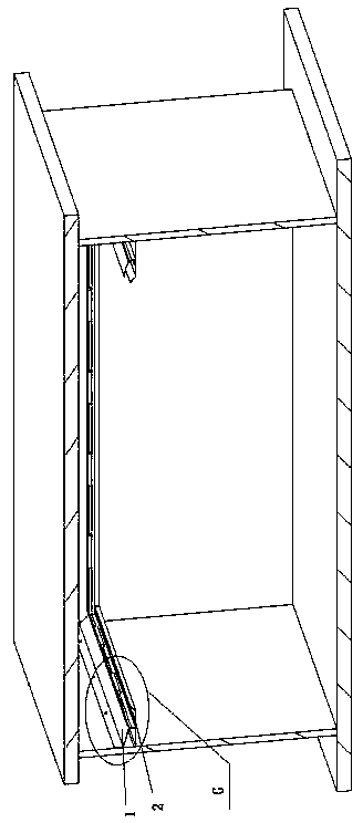
[0036] refer to Figure 1 to Figure 3 , The suspended ceiling of the present invention comprises a suspended ceiling profile 1 and an additional decorative molding 2. The suspended ceiling profile includes a mounting part 3 and a bottom decorative plate 4; the mounting part 3 is a part where the profile is fixed to the wall, and the bottom decorative plate 4 is a profile Looking up at the bottom, the board can be seen. One end of the bottom decorative board 4 is a wall contact part, and the other end extends to form a buckle part 5. The additional decorative molding part 2 is provided with a buckle part 6 to cooperate with the buckle part 5; The upper end of the force-bearing traction part 7 and the wall contact part of the bottom decorative plate 4 are on the same plane; Between the part, the load-bearing traction part 7 is extended from the top to the bottom by the installation part 3, and the bottom of the load-bearing traction part 7 is connected with the bottom decorative...

no. 2 Embodiment

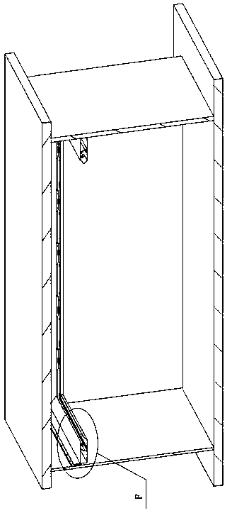
[0039] refer to Figure 4 to Figure 5 , The suspended ceiling of the present invention comprises a suspended ceiling profile 1 and an additional decorative molding 2. The suspended ceiling profile includes a mounting part 3 and a bottom decorative plate 4; the mounting part 3 is a part where the profile is fixed to the wall, and the bottom decorative plate 4 is a profile Looking up at the bottom, the plate can be seen. One end of the bottom decorative plate is a wall contact part, and the other end extends to form a buckle part 5. The additional decorative molding part 2 is provided with a buckle part 6 to cooperate with the buckle part 5; The upper end of the force traction part 7 and the wall contact part of the bottom decorative plate 4 are on the same plane; In the middle part, the force-bearing traction part 7 extends from the installation part 3 from top to bottom, and the bottom of the force-bearing traction part 7 is connected with the bottom decorative plate 4; the fo...

no. 3 Embodiment

[0042] refer to Figure 6 to Figure 7 , The suspended ceiling of the present invention comprises a suspended ceiling profile 1 and an additional decorative molding 2. The suspended ceiling profile includes a mounting part 3 and a bottom decorative plate 4; the mounting part 3 is a part where the profile is fixed to the wall, and the bottom decorative plate 4 is a profile Looking up at the bottom, the plate can be seen. One end of the bottom decorative plate is a wall contact part, and the other end extends to form a buckle part 5. The additional decorative molding part 2 is provided with a buckle part 6 to cooperate with the buckle part 5; The upper end of the force traction part 7 and the wall contact part of the bottom decorative plate 4 are on the same plane; Between the part, the force-bearing traction part 7 extends from the top to the bottom of the installation part 3, and the bottom of the force-bearing traction part 7 is connected with the bottom decorative plate 4; t...


PUM


Abstract

The invention discloses a suspended ceiling. The suspended ceiling is composed of a suspended ceiling sectional material and an additional decoration modeling part. The suspended ceiling sectional material comprises an installation portion and a bottom decoration plate. The installation portion is the portion, fixed to a wall, of the sectional material. The bottom decoration plate is a sheet with the bottom capable of being seen when people look up from the sectional material, one end of the bottom decoration plate is a wall contact portion, and the other end of the bottom decoration plate extends to form a buckling portion. The additional decoration modeling part is provided with a fastening portion matched with the buckling portion. The installation portion, the upper end of a bearing force traction portion and the wall contact portion of the bottom decoration plate are located on the same plane. Due to the fact that the installation portion is the portion fixed to the wall, installation is convenient, a screw mode or a suspension mode is adopted for installation, and installation and fixation are firmer. In addition, the additional decoration modeling part and the suspended ceiling sectional material are provided with notch structures to increase more installation sectional materials, modeling of the suspended ceiling is more diversified and attractive, and the decoration effect is more diversified.

Description

technical field [0001] The invention relates to the field of building decoration engineering, in particular to a suspended ceiling. Background technique [0002] Chinese invention specification CN202936964U discloses a double-layer suspended ceiling, the installation part of which is that one side and the top of the suspended ceiling are respectively pasting surfaces, and the pasting surface of the suspended ceiling is coated with adhesive to be pasted with the wall and the room ceiling and then fixed. However, this method of pasting and fixing has the disadvantages of unreliable pasting, low bearing capacity of the suspended ceiling, and can only be applied to very light products; in addition, the easy aging of the adhesive will also make the structure of the suspended ceiling easy to cause falling accidents. [0003] Chinese Invention Specification CN202577816U discloses a section bar for a suspended ceiling, which includes a molding part, an upper installation part arrang...

Claims


Application Information

Patent Timeline
Patent Type & Authority Applications(China)
IPC IPC(8): E04B9/30E04B9/32
CPCE04B9/30
Inventor 杨东佐
Owner 西大(常熟)研究院有限公司
Why Eureka
Try Eureka