Demolding mechanism of plastic injection mold with convex ring cylindrical product at outer side

An injection mold and demolding mechanism technology is applied in the field of demolding mechanisms for cylindrical products with convex rings on the outside of the injection mold, and can solve the problems of inability to escape the core, the mold cannot be opened normally in sequence, and the work efficiency is affected.

Active Publication Date: 2014-09-10
ZHEJIANG KAIHUA MOLDS
View PDF8 Cites 12 Cited by
  • Summary
  • Abstract
  • Description
  • Claims
  • Application Information

AI Technical Summary

Problems solved by technology

[0002] After the plastic part is injection molded by the injection mold, if the plastic part is cylindrical and the outer wall is made with a convex ring, when the mold is opened, because the cylindrical plastic part has a strong grip on the core, the core will drive the plastic parts, so that the plastic parts stay on the core side, and the convex ring on the outer wall of the plastic part pulls the slanted top block, and the slanted top block pulls the ejector pin plate, so that the mold cannot be opened normally in sequence, and the plastic parts cannot come out of the mold core, thus affecting the next injection molding of the mold, and finally, it is necessary to manually shovel the molded plastic parts from the core, which affects work efficiency, and after the existing plastic parts are injection molded, the plastic parts and waste materials are still connected together and demoulding Finally, it is necessary to manually cut off the waste, which increases the labor intensity of workers

Method used


Image

  • Demolding mechanism of plastic injection mold with convex ring cylindrical product at outer side
  • Demolding mechanism of plastic injection mold with convex ring cylindrical product at outer side
  • Demolding mechanism of plastic injection mold with convex ring cylindrical product at outer side

Examples


Embodiment Construction

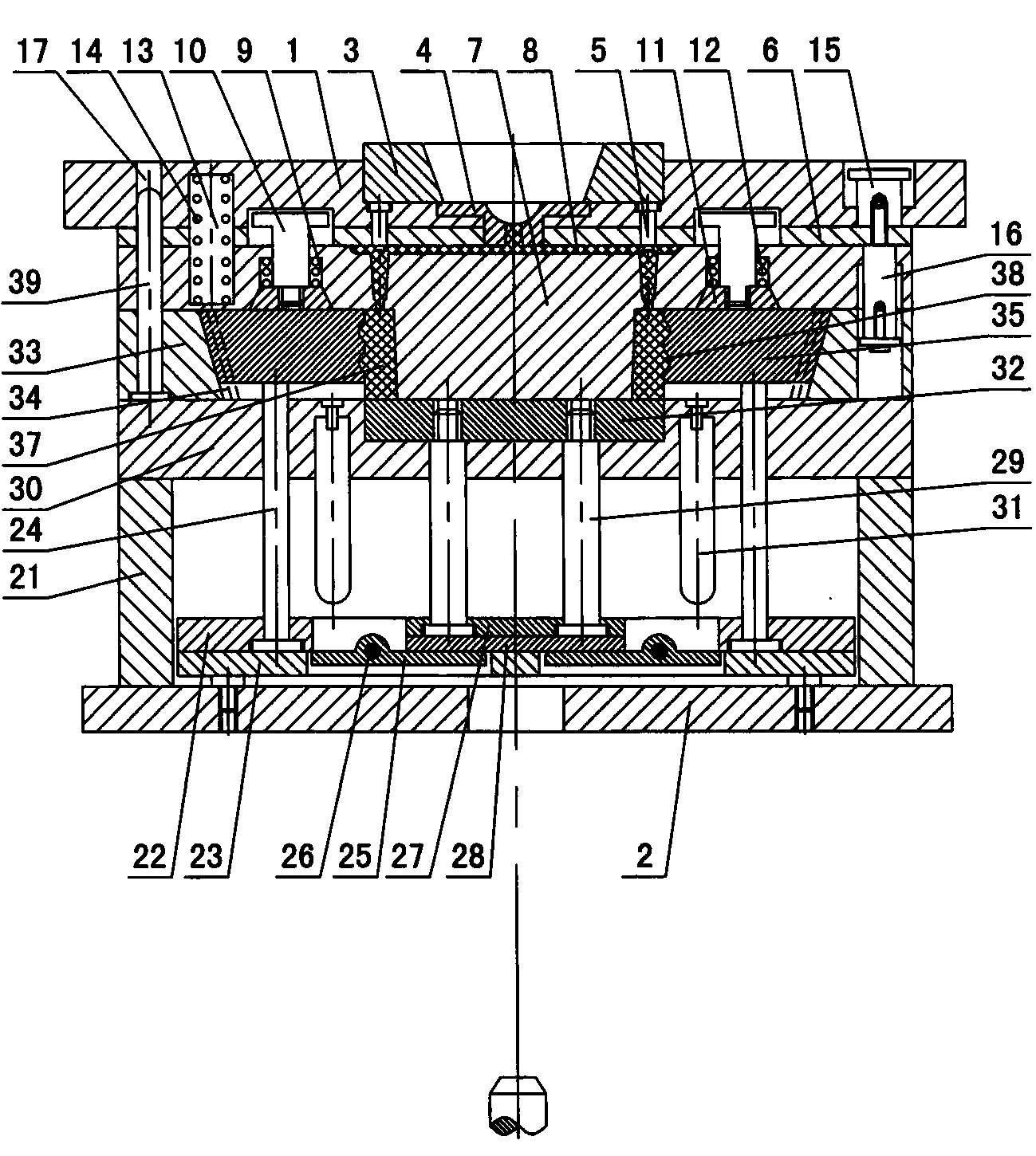
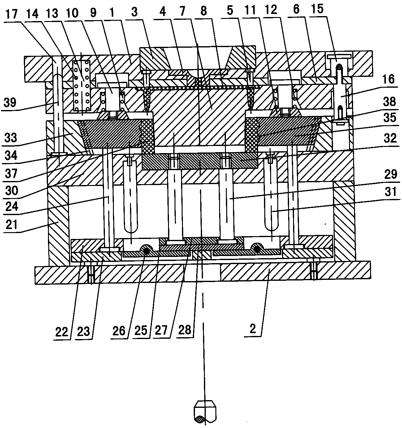
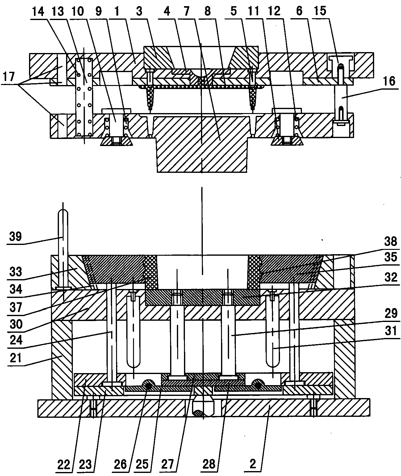
[0012] The invention relates to a demoulding mechanism for a cylindrical product with a convex ring on the outside of an injection mold, such as figure 1 — Figure 5As shown, it is characterized in that it includes an upper doubler plate 1 and a lower doubler plate 2, a positioning ring 3, a gate bushing 4 and a waste pull rod 5 are arranged in the upper doubler plate, a waste push plate 6 is arranged under the upper doubler plate, and the waste pusher A core 7 is arranged under the plate, and there is a waste material 8 between the upper end of the core and the waste material push plate. The distance screw 10, the upper part of the distance screw passes through the bullet block groove and contacts with the top of the core 7, the spring block 11 is connected under the distance screw, and the ejection spring 12 is arranged in the spring block groove on the outer wall of the distance screw to eject The spring is in contact with the upper surface of the spring block 11, and a sp...


PUM


Abstract

The invention discloses a demolding mechanism of a plastic injection mold with a convex ring cylindrical product at the outer side. The demolding mechanism is characterized by comprising an upper compound plate and a lower compound plate, wherein a waste pull rod is arranged in the upper compound plate; a waste push plate is arranged below the upper compound; a core is arranged below the waste push plate; a waste is arranged between the core and the waste push plate; an elastic block groove is formed in the core; a fixed-distance screw is arranged in the elastic block groove; an elastic block is connected below the fixed-distance screw; an ejection spring is arranged outside the fixed-distance screw; spring grooves are formed in the upper compound, the waste push plate and the core; springs are arranged in the spring grooves; a waste push plate fixed-distance push rod and a core fixed-distance pull rod are arranged on the waste push plate; mold feet are arranged on the lower compound; an upper thimble plate and a lower thimble plate are arranged between the mold feet; inclined ejection block ejection rods are mounted on the upper thimble plate and the lower thimble plate; a lever is arranged between the upper thimble plate and the lower thimble plate; a secondary upper ejection plate and a secondary lower ejection plate are arranged on the lower thimble plate; secondary ejection rods are mounted in the secondary upper ejection plate and the secondary lower ejection plate; a plastic piece push plate is arranged in a support plate; the secondary ejection rods are connected with the plastic piece push plate; a cavity is formed in the support plate; a T-shaped inclined groove is formed in the inner side of the cavity, and is connected with an inclined ejection block; and a groove is formed in the inner wall of the inclined ejection block, and is fitted with a convex ring on the outer wall of a plastic piece.

Description

technical field [0001] The invention relates to an injection mold, in particular to a demoulding mechanism for a cylindrical product with a protruding ring outside the injection mold. Background technique [0002] After the plastic part is injection molded by the injection mold, if the plastic part is cylindrical and the outer wall is made with a convex ring, when the mold is opened, because the cylindrical plastic part has a strong grip on the core, the core will drive the plastic parts, so that the plastic parts stay on the core side, and the convex ring on the outer wall of the plastic part pulls the slanted top block, and the slanted top block pulls the ejector pin plate, so that the mold cannot be opened normally in sequence, and the plastic parts cannot come out of the mold core, thus affecting the next injection molding of the mold, and finally, it is necessary to manually shovel the molded plastic parts from the core, which affects work efficiency, and after the exis...

Claims


Application Information

Patent Timeline
Patent Type & Authority Applications(China)
IPC IPC(8): B29C45/40
CPCB29C45/33B29C45/4005
Inventor 梁正华
Owner ZHEJIANG KAIHUA MOLDS
Why Eureka
Try Eureka