Broken rope catching device
A technology for breaking ropes and steel ropes, applied in transportation and packaging, cable railways, motor vehicles, etc., can solve problems such as broken ropes and threats to production safety in coal mines, and achieve safety accidents, simple structure, and small losses in safety accidents Effect
- Summary
- Abstract
- Description
- Claims
- Application Information
AI Technical Summary
Problems solved by technology
Method used
Image

Examples
Embodiment 1
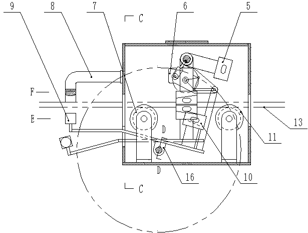
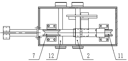
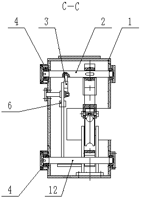
[0022] Such as Figure 1-Figure 6 As shown, the broken rope arresting device includes a box body 1, an upper wedge shaft 2, a reaction arm shaft 12, a latch 3, an upper wedge 5, a reaction arm 9, a lower wedge 10, a lever linkage mechanism 6, a first bracket The sheave 7 and the second supporting sheave 11, the upper wedge shaft 2 is installed on the top of the casing 1, the reaction arm shaft 12 is installed on the bottom of the casing 1, and the upper wedge shaft 2 and the reaction arm shaft 12 are not on the same vertical plane, the first sheave 7 and the second sheave 11 are installed at the bottom of the box 1 at intervals, and the first sheave 7 and the second sheave 11 are located on the same straight line Above, the installation height of the first sheave 7 and the second sheave 11 is higher than the reaction arm shaft 12, and the limit arm 8 is installed on the side where the first sheave 7 is installed on the box body 1. Position arm 8 is positioned at the top of re...
Embodiment 2
[0027] Such as Figure 1-Figure 6 As shown, the broken rope arresting device includes a box body 1, an upper wedge shaft 2, a reaction arm shaft 12, a latch 3, an upper wedge 5, a reaction arm 9, a lower wedge 10, a lever linkage mechanism 6, a first bracket The sheave 7 and the second supporting sheave 11, the upper wedge shaft 2 is installed on the top of the casing 1, the reaction arm shaft 12 is installed on the bottom of the casing 1, and the upper wedge shaft 2 and the reaction arm shaft 12 are not on the same vertical plane, the first sheave 7 and the second sheave 11 are installed at the bottom of the box 1 at intervals, and the first sheave 7 and the second sheave 11 are located on the same straight line Above, the installation height of the first sheave 7 and the second sheave 11 is higher than the reaction arm shaft 12, and the limit arm 8 is installed on the side where the first sheave 7 is installed on the box body 1. Position arm 8 is positioned at the top of re...
Embodiment 3
[0033] Such as Figure 1-Figure 6 As shown, the broken rope arresting device includes a box body 1, an upper wedge shaft 2, a reaction arm shaft 12, a latch 3, an upper wedge 5, a reaction arm 9, a lower wedge 10, a lever linkage mechanism 6, a first bracket The sheave 7 and the second supporting sheave 11, the upper wedge shaft 2 is installed on the top of the casing 1, the reaction arm shaft 12 is installed on the bottom of the casing 1, and the upper wedge shaft 2 and the reaction arm shaft 12 are not on the same vertical plane, the first sheave 7 and the second sheave 11 are installed at the bottom of the box 1 at intervals, and the first sheave 7 and the second sheave 11 are located on the same straight line Above, the installation height of the first sheave 7 and the second sheave 11 is higher than the reaction arm shaft 12, and the limit arm 8 is installed on the side where the first sheave 7 is installed on the box body 1. Position arm 8 is positioned at the top of re...
PUM
 Abstract
Description
Claims
Application Information
 - R&D Engineer
- R&D Manager
- IP Professional
- Industry Leading Data Capabilities
- Powerful AI technology
- Patent DNA Extraction
Browse by: Latest US Patents, China's latest patents, Technical Efficacy Thesaurus, Application Domain, Technology Topic.
© 2024 PatSnap. All rights reserved.Legal|Privacy policy|Modern Slavery Act Transparency Statement|Sitemap