
Windlass steel cable detection device and method

A detection device and detection method technology, applied in measuring devices, material analysis through optical means, instruments, etc., can solve the problems of threats to the normal operation of steel cables, too many steel cables, difficult construction, etc., and achieve the goal of eliminating ambient light Interference, simple effect of image recognition algorithm

Active Publication Date: 2014-09-10
深圳市云特科技有限公司
View PDF9 Cites 4 Cited by
  • Summary
  • Abstract
  • Description
  • Claims
  • Application Information

AI Technical Summary

Problems solved by technology

[0003] 1. The contact cable integrity detection method is difficult to construct, and the contact installation of the cable will lead to an additional failure point for the cable
[0004] 2. The non-contact steel cable integrity detection method generally uses the photoelectric cross-beam shielding type. The photoelectric cross-beam type needs to be installed about 10 cm away from the steel cable, which also poses a threat to the normal operation of the steel cable.

Method used


Image

  • Windlass steel cable detection device and method
  • Windlass steel cable detection device and method
  • Windlass steel cable detection device and method

Examples


Embodiment Construction

[0020] The present invention will be described in further detail below in conjunction with specific embodiments and accompanying drawings. Embodiments of the present invention are described in detail below, examples of which are shown in the drawings, wherein the same or similar reference numerals designate the same or similar elements or elements having the same or similar functions throughout. The embodiments described below with reference to the accompanying drawings are exemplary, and are only used to explain the technical solution of the present invention, and should not be construed as limiting the present invention.

[0021] In the description of the present invention, the orientation or positional relationship indicated by the terms "inner", "outer", "longitudinal", "transverse", "upper", "lower", "top", "bottom" etc. are based on the drawings The orientations or positional relationships shown are only for the convenience of describing the invention and do not require ...


PUM


Abstract

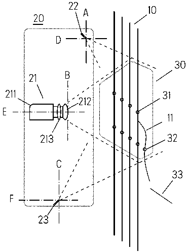
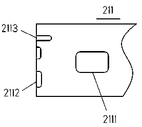
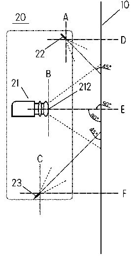
The invention provides a windlass steel cable detection device. The windlass steel cable detection device comprises an image collection unit which is installed on the front surface of a windlass steel cable, wherein the image collection unit comprises an imaging instrument, an upper laser and a lower laser, the imaging instrument is arranged between the upper laser and the lower laser and a distance is kept between the imaging instrument and the steel cable, the imaging instrument is provided with a lens and adopts the steel cable as a collection target, the upper laser and the lower laser are identical components and arranged in front of and behind the lens, the upper laser and the lower laser are respectively provided with a luminescent hole, each luminescent hole faces the imaging instrument collection target by forming an angle with the target, a light curtain projected by each luminescent hole is overlapped with an imaging instrument collection target area to form an overlapped area, and the overlapped area is a spot area. By adopting the structure, the technical problems of error in judgment and judgment by mistake caused by collecting abnormal light spots can be solved, so that a good effect for improving the accuracy in detection can be realized.

Description

technical field [0001] The invention relates to the technical field of operation transportation, in particular to a hoist wire cable detection device and a method thereof. Background technique [0002] The steel cable integrity detection method of prior art has: [0003] 1. The contact type steel cable integrity detection method is difficult to construct, and the contact installation of the steel cable will cause an additional failure point for the steel cable. [0004] 2. The non-contact steel cable integrity detection method generally uses the photoelectric cross-beam shielding type. The photoelectric cross-beam type needs to be installed about 10 cm away from the steel cable, which also poses a threat to the normal operation of the steel cable. Contents of the invention [0005] In order to solve the above technical problems, the main purpose of the present invention is to provide a hoist wire cable detection device and method thereof that can improve detection accurac...

Claims


Application Information

Patent Timeline
Patent Type & Authority Applications(China)
IPC IPC(8): G01N21/892
Inventor 戢波林维专
Owner 深圳市云特科技有限公司
Learn More