
Large-diameter pipeline transport cart

A technology for large-diameter pipelines and transport vehicles, which is applied in the fields of electric power construction and construction to achieve the effect of improving construction safety and operability, avoiding horizontal torque problems and ensuring stability.

Active Publication Date: 2014-09-17
牛永杰
View PDF5 Cites 1 Cited by
  • Summary
  • Abstract
  • Description
  • Claims
  • Application Information

AI Technical Summary

Problems solved by technology

[0008] Aiming at the problem of horizontal transportation of large-diameter pipelines in the current construction process, the present invention discloses a large-diameter pipeline transportation vehicle, which is composed of the following components:

Method used


Image

  • Large-diameter pipeline transport cart
  • Large-diameter pipeline transport cart

Examples


Embodiment 1

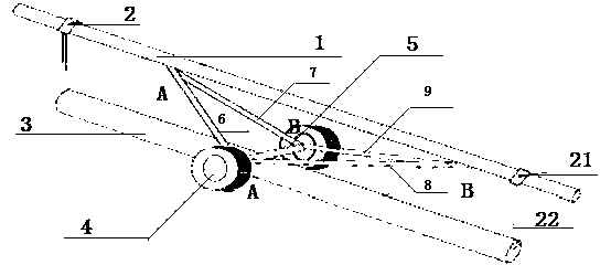
[0026] like figure 1 As shown, a large-diameter pipeline transport vehicle is composed of the following components:

[0027] ——The support rod 1, the two ends of the support rod 1 are provided with clamping fixtures 2, and the clamping fixtures 2 fixedly connect the pipe 3 and the support rod 1 into a moving whole;

[0028] - wheel set 4, said wheel set is composed of a pair of rollers arranged in pairs, the axes of said two rollers are respectively fixed at the two ends of a rotating shaft 5;

[0029] ——Fixed support frame group, described fixed support frame group is made up of the first connecting rod 6, the second connecting rod 7, the third connecting rod 8, the fourth connecting rod 9, the two ends of the first connecting rod 6 respectively fixed on the A end of the rotating shaft and the support rod A point, the two ends of the second connecting rod 7 are respectively fixed on the B end of the rotating shaft and the supporting rod A point, and the two ends of the third...

Embodiment 2

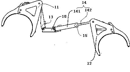
[0033] On the basis of the structure of Embodiment 1, we specifically disclose a more stable way of clamping the fixture, such as figure 2 As shown in , it consists of a connection base 10, a first handle 11 fixed to the connection base 10, and a second handle 12, and the first handle 11 and the second handle 12 are respectively fixed by respective connecting rods. In the connecting seat 10, the connecting rod is a sleeve-type structure, and the inner and outer sleeves can slide relative to each other. There is a hole at the top of the outer sleeve, and a locking screw is also included. The hole diameter at the top of the cylinder matches. exist figure 2 , we can see that for the first gripper 11, the connecting rod is 13, at this time the outer sleeve and the inner sleeve are completely overlapped together, and for the second gripper 12, the connecting rod is 14 , at this moment, the outer sleeve 141 and the inner sleeve 142 are in a state of partially sliding out, and th...

Embodiment 3

[0038] On the basis of embodiment 1 or embodiment 2, especially embodiment 2, a pick rod is further included, and the pick rod is grasped by the first gripper 11 or the second gripper 12 to form a horizontal rod body.

[0039]


PUM


Abstract

The invention belongs to the field of construction, and relates to the field of power construction, in particular to a large-diameter pipeline transport cart. The large-diameter pipeline transport cart aims to achieve horizontal transportation of a large-diameter pipeline in an existing construction process. The large-diameter pipeline transport cart is composed of a supporting rod, a wheel set and a fixed support frame, wherein the two ends of the supporting rod are respectively provided with a clamping fastener, and the pipeline is fixedly connected with the supporting rod into a movement whole through the clamping fasteners; the wheel set is composed of a set of idler wheels arranged in pairs, and the axes of the two idler wheels are fixed to the two ends of a rotary shaft respectively. After the technical scheme is adopted, actual possibility of ground transportation of the large-diameter pipeline is achieved, and therefore the problem of horizontal torque which is easily caused in a hoisting process is solved, and construction safety and operability are enhanced.

Description

[0001] technical field [0002] The invention belongs to the field of construction, in particular to the field of electric power construction, and more specifically relates to a large-diameter pipeline transport vehicle. [0003] Background technique [0004] Large-diameter pipes refer to pipes with larger diameters. Generally speaking, large-diameter pipes are made of seamless steel pipes and welded seam steel pipes, which are formed by painting the outer wall. [0005] Generally speaking, we use pipelayers to transport and deploy pipelines during construction. However, large-diameter pipelines are prone to horizontal torque forces during hoisting due to their large volume and large diameter, which affects construction safety and construction accuracy. have an impact. This phenomenon is especially reflected in the need for horizontal lifting of large diameters. In order to reduce this horizontal torque, the current method used in construction is to increase the length of ...

Claims


Application Information

Patent Timeline
Patent Type & Authority Applications(China)
IPC IPC(8): B62B1/26B62B1/14
Inventor 牛永杰
Owner 牛永杰
Learn More