
Stirring shaft upper end gas supply cutting device

A technology of cutting device and stirring shaft, which is applied to mixers with rotating stirring devices, accessories of mixers, transportation and packaging, etc. Simple, meet the needs of use, reduce energy consumption

Pending Publication Date: 2019-09-17
SHANGHAI SHANJIA MACHINERY EQUIP
View PDF0 Cites 0 Cited by
  • Summary
  • Abstract
  • Description
  • Claims
  • Application Information

AI Technical Summary

Problems solved by technology

[0002] The fast cutting of glue is very important in the glue supply process. It is required to be sensitive to avoid glue dripping and wire drawing at the glue injection head. The existing cutting devices generally use two-way pneumatics to realize the lifting of the stirring shaft. On the one hand, High energy consumption, on the other hand, the lifting height of the stirring shaft cannot be adjusted, which cannot meet the needs of use

Method used


Image

  • Stirring shaft upper end gas supply cutting device

Examples


Embodiment Construction

[0013] In order to easily understand the technical means, creative features, goals and effects of the present invention, the present invention will be further described below in conjunction with specific illustrations.

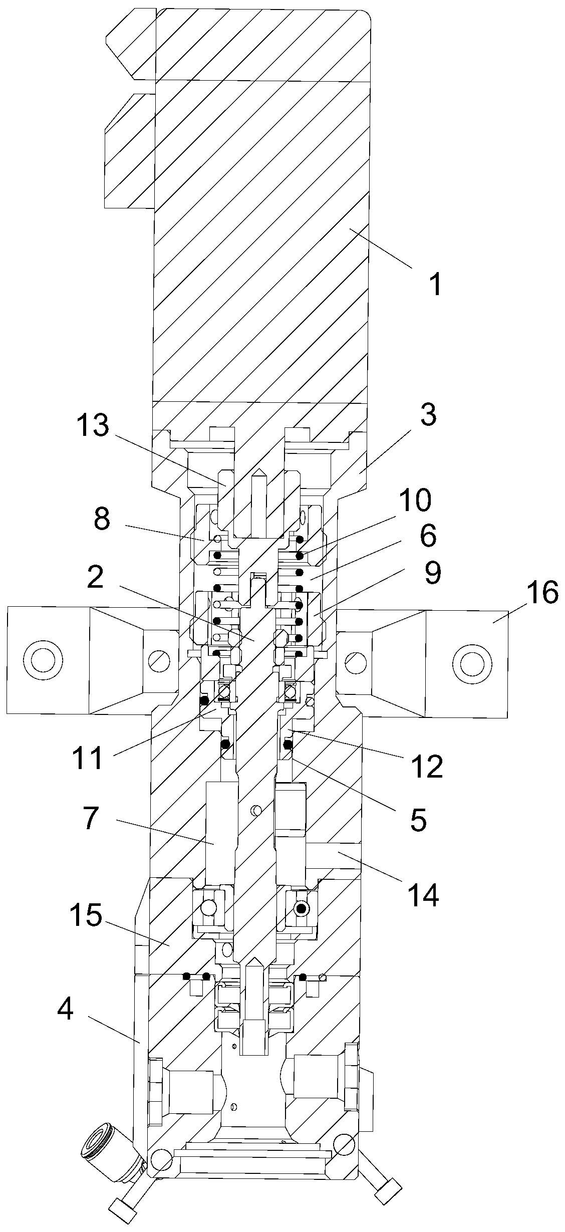
[0014] Such as figure 1 As shown, a gas supply cut-off device at the upper end of the stirring shaft 2 includes a motor 1, a stirring shaft 2, a guide seat 3 and a base 4, the guide seat 3 is hollow, and a step 5 is provided inside the guide seat 3 to divide its interior into an upper guide Cavity 6 and lower air chamber 7, the spring strength adjustment seat 8, the gap adjustment seat 9, the return spring 10 and the bearing positioning seat 11 are installed in the guide chamber sequentially from top to bottom, the spring strength adjustment seat 8, the gap adjustment The outer peripheral surface of the seat 9 is threadedly connected with the inner peripheral surface of the guide cavity. There is a bearing in the bearing locating seat 11, and the lower end sur...


PUM


Abstract

The invention discloses a stirring shaft upper end gas supply cutting device, and belongs to the field of cutting device. The stirring shaft upper end gas supply cutting device comprises a motor, a stirring shaft, a guide seat, and a pedestal; the guide seat is hollow, a step is arranged in the hollow guide seat to divide the guide seat into an upper guiding chamber and a lower gas chamber; in the upper guiding chamber, a spring force adjusting seat, a gap adjusting seat, a return spring, and a bearing positioning seat are arranged successively from top to bottom; the periphery surface of the spring force adjusting seat, and the periphery surface of the gap adjusting seat are connected with the inner surface of the upper guiding chamber through thread connection; a bearing is arranged in the bearing positioning seat; the lower end surface of the bearing positioning seat is provided with a flange matching the step; and dynamic sealing is formed between the bearing positioning seat and the inner wall of the upper guiding chamber, and the flange and the step. According to the stirring shaft upper end gas supply cutting device, gas supply uplifting and return spring down-pressing are adopted to realize rising and falling reciprocating motion of the stirring shaft; the structure is simple; unnecessary energy consumption is reduced; the lifting height of the stirring shaft can be adjusted, and using requirements are satisfied.

Description

technical field [0001] The invention relates to an air supply cutting device at the upper end of a stirring shaft, which belongs to the field of cutting devices. Background technique [0002] The fast cutting of glue is very important in the glue supply process. It is required to be sensitive to avoid glue dripping and wire drawing at the glue injection head. The existing cutting devices generally use two-way pneumatics to realize the lifting of the stirring shaft. On the one hand, The energy consumption is relatively high. On the other hand, the lifting height of the stirring shaft cannot be adjusted, which cannot meet the needs of use. Contents of the invention [0003] The technical problem to be solved by the present invention is to provide an air supply cut-off device at the upper end of the stirring shaft, which realizes the lifting and reciprocating motion of the stirring shaft by means of the upper end of the air supply and the pressing down of the return spring, w...

Claims


Application Information

Patent Timeline
IPC IPC(8): B01F7/16B01F15/00
CPCB01F27/806B01F35/00
Inventor 熊俊兰左天地
Owner SHANGHAI SHANJIA MACHINERY EQUIP
Learn More