

Tire conveying system
A conveying system and tire technology, applied in the direction of transportation, packaging, loading/unloading, etc., can solve problems such as unsafe, error-prone, and unable to keep up with the beat requirements of the main engine factory, and achieve stable and safe tire transportation, reasonable angle and length Effect
Inactive Publication Date: 2014-09-17
YIZHENG SHENDI IND DEV
View PDF0 Cites 2 Cited by
- Summary
- Abstract
- Description
- Claims
- Application Information
AI Technical Summary
Problems solved by technology
[0002] Existing products use forklifts to fork the tire assembly in the material rack to the back of the box-type conveyor truck for sorting on the truck.
Method used
View moreImage
Smart ImageViewing Examples

Examples
Embodiment Construction
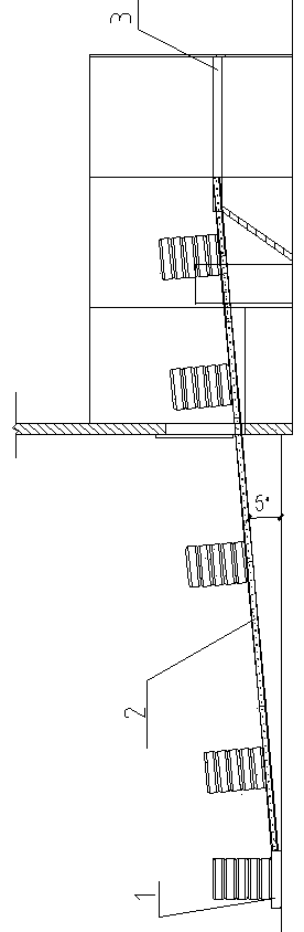
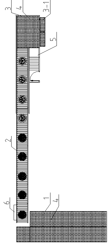
[0008] Such as figure 1 , 2 As shown, the present invention includes a first platform 1, a conveying device 2 connected to the output end of the first platform 1, a second platform 3 connected to the output end of the conveying device 2; the end of the conveying device 2 close to the first platform 1 is lower At one end close to the second platform 3, the angle between the conveying device 2 and the horizontal plane is 5°; on the top surfaces of the first platform 1 and the second platform 3, several rows of universal balls 4 are respectively distributed; the second platform 3 includes docking The turning plate 3-1 is hinged to the output end of the second platform 3;
Login to View More PUM
 Abstract
The invention provides a tire conveying system, which relates to the technical field of sequenced tire conveyance of a tire assembly split charging line. The tire conveying system comprises a first platform, a conveying device, and a second platform, wherein the conveying device is connected with the output end of the first platform, the second platform is connected with the output end of the conveying device, one end, near the first platform, of the conveying device is lower than one end near the second platform, an included angle between the conveying device and the horizontal plane is 5 degrees, a plurality of lines of universal rolling balls are respectively distributed on the top surfaces of the first platform and the second platform, the second platform comprises a butt joint turning plate, the butt joint turning plate is hinged to the output end of the second platform, a manual operation room is arranged at one side of the output end of the second platform, and the conveying device is driven through a variable-frequency motor. The tire conveying system has the advantages that the conveying device is in inclined arrangement, the angle and the length are more reasonable, and the conveyance of tires is stable and safe.
Description
technical field [0001] The invention relates to the technical field of sorting and conveying tires in a tire assembly line. Background technique [0002] Existing products use a forklift to fork the tire assembly in the material rack to the back of the box-type conveyor truck for sorting on the truck. Contents of the invention [0003] The object of the present invention is to provide a time-saving, labor-saving, safe and convenient tire conveying system for the above defects. [0004] The present invention comprises a first platform, a conveying device connected to the output end of the first platform, and a second platform connected to the output end of the conveying device; the end of the conveying device close to the first platform is lower than the end close to the second platform, The included angle between the conveying device and the horizontal plane is 5°; several rows of universal balls are respectively distributed on the top surfaces of the first platform and t...
Claims
Login to View More Application Information
Patent Timeline
 Patent Type & AuthorityApplications(China)
IPC IPC(8): B65G67/04
CPCY02P70/10
Inventor张淮平俞增宏李鼎伟李敏藤立里
OwnerYIZHENG SHENDI IND DEV