Special tool and method for installing electric power circuit weight-increasing hammer

A technology of power lines and special tools, applied in the direction of overhead lines/cable equipment, etc., can solve problems such as poor fixation, difficulty, and insufficient strength, and achieve the effects of not easy to fall off, low labor intensity, and high installation efficiency

Active Publication Date: 2013-06-12
STATE GRID CORP OF CHINA +2
View PDF3 Cites 0 Cited by
  • Summary
  • Abstract
  • Description
  • Claims
  • Application Information

AI Technical Summary

Problems solved by technology

When working with a heavy hammer on the line, the operator needs to complete the work of adjusting the distance between the wires, installing the suspension clamp, and disassembling the insulator on the ladder, which has caused the following problems: 1. The weight of the heavy hammer is 33 kg. The square iron block is not easy to fix, and it is easy to fall off during the transfer process; 2. The width of the weight is larger than the distance between the drainage lines. During the installation process, the upper and lower parts of the weight need to be loosened. After the drainage line is pulled apart, it is inserted into the weight The wire is stuck in the groove, and these operations are difficult to complete on the ladder. If the operator is not strong enough or experienced, it may even fail to complete the operation, or cause the weight to fall off; 3. After the operator puts the wire into the weight, if The position is not suitable, and it needs to be adjusted properly. It is very difficult to move a 33 kg weight on the ladder

Method used


Image

  • Special tool and method for installing electric power circuit weight-increasing hammer
  • Special tool and method for installing electric power circuit weight-increasing hammer
  • Special tool and method for installing electric power circuit weight-increasing hammer

Examples


Embodiment Construction

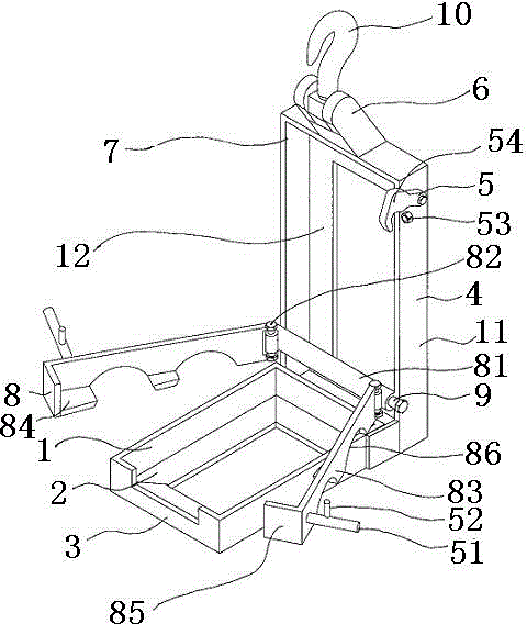
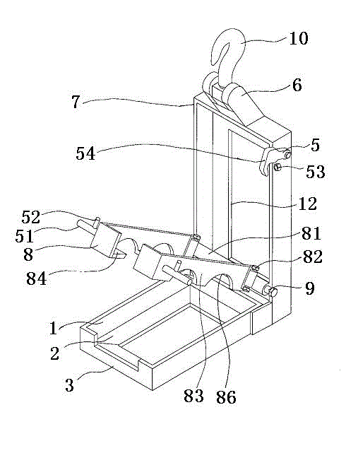
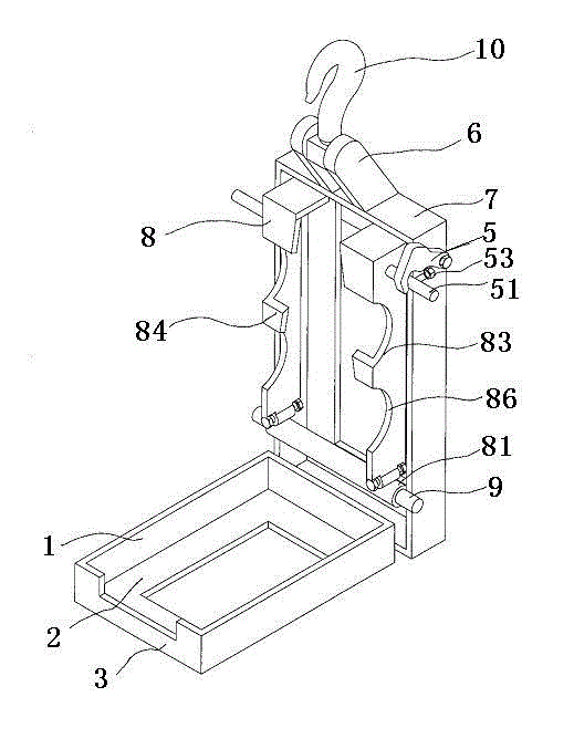
[0024] The structure of the special tool for installing the power line weight hammer proposed by the present invention will be further described below in conjunction with the accompanying drawings.

[0025] Such as figure 1 , figure 2 with image 3 As shown, it is a structural schematic diagram of a special tool for installing a power line weight hammer. Its structure includes a lower hammer bracket 3 with a first frame 1 and a bottom bracket 2, and an upper hammer fixing frame 4 perpendicular to the bottom bracket 2 is arranged at the rear end of the lower hammer bracket 3. The upper hammer fixing bracket 4 consists of The upper frame body 7 formed by the second frame 11 and the baffle plate 12 and the upper hammer swing frame 8 positioned at the front of the upper frame body 7 are provided with a horizontal fixed shaft 9 near the lower end of the upper frame body 7. The swing base 81 that the fixed shaft 9 rotates and the two side swing frames 83 that are connected to th...


PUM


Abstract

The invention belongs to the technical field of weight-increasing hammer installing tools and methods, and discloses a special tool and method for installing an electric power circuit weight-increasing hammer. The special tool is mainly technically characterized by comprising a lower hammer bracket and an upper hammer fixing frame vertical to the lower hammer bracket, wherein the upper hammer fixing frame comprises an upper frame body composed of a second frame and a baffle plate and an upper hammer swinging frame arranged in front of the upper frame body, a fixed shaft in a horizontal direction is arranged at the place, close to the lower end of the upper frame body, the upper hammer swinging frame comprises a swinging base capable of rotating around the fixed shaft and two side swinging frames connected through a first pin roll, a lower flanging and a front flanging are respectively arranged below and at the front end parts of the side swinging frames, two lead slots are respectively formed below the side swinging frames, a hook is arranged above the frame body, and a swinging frame locking mechanism is arranged at the side surface of the frame body. The weight-increasing hammer is fixed on the ground, a lead is clamped in thread holes in an upper hammer and a lower hammer, and then the lower flanging and the front flanging of the side swinging frames are separated from the hammers and the hammers are easily installed, and thus the installing efficiency is high, the labor intensity is little, and the hammers do not easily fall off in a transferring process.

Description

technical field [0001] The invention belongs to the technical field of a special tool for installing a power line weight hammer and an installation method, and in particular relates to a special tool for installing a power line weight hammer and an installation method. Background technique [0002] On the power line, in order to prevent the line from swinging, a weighted hammer is installed on the line. When working with a heavy hammer on the line, the operator needs to complete the work of adjusting the distance between the wires, installing the suspension clamp, and disassembling the insulator on the ladder, which has caused the following problems: 1. The weight of the heavy hammer is 33 kg. The square iron block is not easy to fix, and it is easy to fall off during the transfer process; 2. The width of the weight is larger than the distance between the drainage lines. During the installation process, the upper and lower parts of the weight need to be loosened. After the d...

Claims


Application Information

Patent Timeline
Patent Type & Authority Applications(China)
IPC IPC(8): H02G1/02
Inventor 赵建辉宋龙堂何义良尚建广王进朝白龙魏朋李树平刘明亮
Owner STATE GRID CORP OF CHINA
Why Eureka
Try Eureka