Soft insulating sheath of wire

A technology of insulating sheaths and wires, applied in the field of power transmission and transformation, can solve the problems of low difficulty in installation and construction, heavy load due to false construction of wires and original insulators, increased tripping, etc., and achieve the effect of increasing insulation protection performance

Pending Publication Date: 2019-12-06
XIANGYANG GUOWANG COMPOSITE INSULATORS
View PDF0 Cites 0 Cited by
  • Summary
  • Abstract
  • Description
  • Claims
  • Application Information

AI Technical Summary

Problems solved by technology

At present, the following measures are adopted in the project to address this situation: 1. Install two angle steels at the cross-arm head, install a string of insulators on the outside after extending the cross-arm head, and pull the linear insulator strings outward to form an inverted right-angled triangle. This method is economical and effective, but it is difficult to install and construct; 2. Install a porcelain cross-arm at the position of the tower body and the conductor to support the conductor to balance the horizontal pressure of the wind. This method is less difficult to install and construct, and the effect is better. Well, it is more economical, but the construction of the wire and the original insulator is falsely loaded, and the design and processing are greatly affected by the length of the cross arm; 3. Install a stay wire outside the wire below to balance the horizontal pressure of the wind. It is economical, easy to install, and the effect is good, but the wire and the original insulator are fake, and the load is relatively large, which affects farmers' cultivation, and the safety and reliability are poor.
The above methods of preventing wind damage all have a disadvantage, that is, adding insulators while preventing wind, and increasing the possibility of tripping due to the failure of wind deflection insulators while preventing wind deflection. Therefore, it is a passive preve

Method used


Image

  • Soft insulating sheath of wire
  • Soft insulating sheath of wire
  • Soft insulating sheath of wire

Examples


Example Embodiment

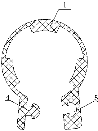
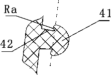
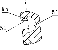
[0022] figure 1 , 2 , 3, 4, the sleeve body 1 is a hose, there are three boss ribs in the hose tube wall, a heat dissipation gap 3 is formed between the two adjacent boss ribs, and a pipe gap is provided on the hose wall. There are two connecting handles extending radially on both sides of the seam. When the two connecting handles move relative to the two ends of the pipe seam, the boss ribs in the inner cavity of the hose enclose a positioning space for positioning the wire. When the two ends of the pipe joint are separated, the boss ribs of the inner cavity of the hose enclose an assembly space for fitting the wires, and the two connecting handles are provided with connecting parts for connecting. There are fasteners on the connecting handle. The fasteners include a male buckle 4 and a female buckle 5 for easy buckling. The hook-shaped part Ra formed on the back of the male buckle 4 and the hook-shaped part Rb formed on the back of the female buckle 5 prevent detachment after ...


PUM


Abstract

The utility model discloses a soft insulating sheath of a wire. The sheath comprises a sheath body which is a hose, and more than three boss ribs are arranged in the wall of the hose; a heat dissipation gap is formed between every two adjacent boss ribs; a pipe seam is formed in the wall of the hose; two connecting handles extend from two sides of the hose seam in the radial direction; when the two connecting handles relatively move to be attached to the two end faces of the pipe seam, the boss ribs of the inner cavity of the hose define a positioning space used for positioning the wire; whenthe two connecting handles oppositely move to be separated from the two end faces of the pipe seam, the boss ribs of the inner cavity of the hose define an assembling space used for being matched withwire assembling; and connecting pieces used for connection are arranged on the two connecting handles. According to the invention, the problems of deformation, burnthrough, burnout and the like of the soft insulating sheath of the wire for preventing wind damage, bird damage and collision at high temperature due to the fact that heat cannot be uniformly diffused when the insulating sheath works on the wire are solved. The sheath plays an important role in guaranteeing safe and stable energy conveying.

Description

technical field [0001] The invention belongs to the technical field of power transmission and transformation, and relates to a wire insulating sheath. Background technique [0002] my country's overhead transmission lines mostly pass through inaccessible mountains and plains. For economic considerations, transmission and distribution lines have bare wires erected in these areas. Because there is no sheath, it is conducive to heat dissipation. And birds stay and cause guano to accumulate, causing wind damage and bird damage accidents, resulting in line leakage, flashover phenomenon, and potential safety hazards. [0003] The reason for the wind damage fault is that the strong wind is perpendicular to the direction of the line, which blows the wires away, and discharges when the distance from the tower components is less than the safe distance, resulting in a ground fault and tripping of the line. At present, the following measures are adopted in the project to address this si...

Claims


Application Information

Patent Timeline
IPC IPC(8): H01B17/58H02G7/00
CPCH01B17/58H02G7/00
Inventor 吴兆峰杨红军王锋田正波刘江甘银银
Owner XIANGYANG GUOWANG COMPOSITE INSULATORS
Why Eureka
Try Eureka