Detachable connection device, and the connection device of the corresponding wire harness connector and buckle
A wire harness connector and disassembly connection technology, which is applied to the parts, connections, coupling devices and other directions of the connection device, can solve the problems of limited application scope, large space occupied by the frame bracket, inconvenient disassembly, etc., and achieves compact structure, guaranteed Assembly accuracy and connection reliability, and the effect of firm fixation
- Summary
- Abstract
- Description
- Claims
- Application Information
AI Technical Summary
Problems solved by technology
Method used
Image

Examples
Embodiment 1
[0050] Embodiment 1 A connection device between a wire harness connector and a buckle
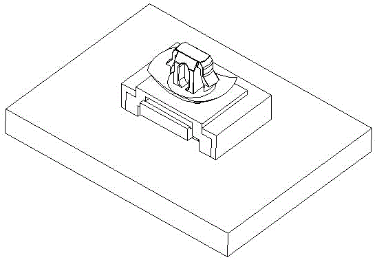
[0051] This embodiment is used for connecting the wire harness connector 5 and the buckle 4 .
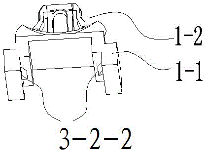
[0052] see Figure 10 , the buckle 4 is an existing structure with a fixed hook 1-2.
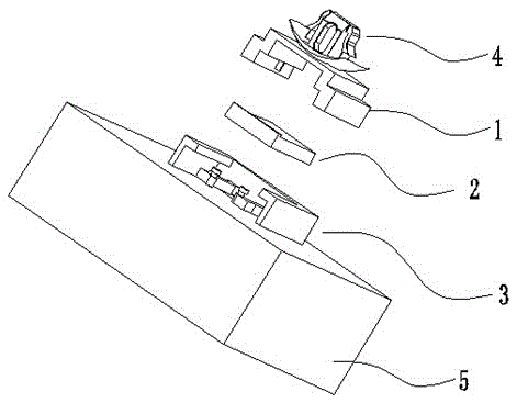
[0053] like figure 1 As shown, this embodiment includes a fixed platform 3 fixedly connected with the wire harness connector 5 , a base 1 - 1 fixedly connected with the buckle 4 , and a slider 2 slidably fitted with the fixed platform 3 .
[0054] The fixed platform 3, the abutment 1-1, and the slider 2 are arranged separately from each other, such as figure 2 shown.
[0055] In order to facilitate the description of the relative positional relationship between components, the directions and orientations of up, down, left, right, front, and rear described below are based on the attached drawings as an example, and are not absolute positions of related components or the positional relationship between compo...
Embodiment 2
[0079] Embodiment 2 A connection device between a wire harness connector and a buckle
[0080] This embodiment is used for connecting the wire harness connector and buckle, and includes a fixed platform fixedly connected with the wire harness connector, a base fixedly connected with the buckle, and a slider capable of slidingly mating with the fixed platform. The fixed table, the abutment, and the slide block are arranged separately from each other.
[0081] In order to facilitate the description of the relative positional relationship between components, the directions and orientations of up, down, left, right, front and rear described below are only a designated reference, not specific references to the absolute positions of related components and the positional relationship between components , "Back" refers to the direction that the vertical paper faces the reader, and "front" refers to the direction that the vertical paper faces away from the reader.
[0082] ①Abutment ...
Embodiment 3
[0105] Embodiment 3 A detachable connection device
[0106] This embodiment is used to connect the first component and the second component of the wire, and includes a fixed platform fixedly connected with the first component, a base fixedly connected with the second component, and a slider slidably matched with the fixed platform. The fixed table, the abutment, and the slide block are arranged separately from each other.
[0107] In order to facilitate the description of the relative positional relationship between components, the directions and orientations of up, down, left, right, front, and rear described below are only designated references for describing relative positional relationships, not for relative components and absolute positional relationships between components. Position specifically refers to, "back" refers to the direction vertical to the reader, and "front" refers to the direction away from the reader.
[0108] ①Fixed table
[0109] The fixed table has a...
PUM
 Abstract
Description
Claims
Application Information
 - R&D
- Intellectual Property
- Life Sciences
- Materials
- Tech Scout
- Unparalleled Data Quality
- Higher Quality Content
- 60% Fewer Hallucinations
Browse by: Latest US Patents, China's latest patents, Technical Efficacy Thesaurus, Application Domain, Technology Topic, Popular Technical Reports.
© 2025 PatSnap. All rights reserved.Legal|Privacy policy|Modern Slavery Act Transparency Statement|Sitemap|About US| Contact US: help@patsnap.com