Non-retention plunger injection storage cylinder structure of injection moulding machine

A material storage cylinder and injection molding machine technology, which is applied in the field of plunger injection structure of injection molding machines, to achieve the effects of simple and reasonable structure, improved work efficiency and yield, and convenient maintenance

Active Publication Date: 2014-09-24
广东伊之密精密注压科技有限公司
View PDF5 Cites 6 Cited by
  • Summary
  • Abstract
  • Description
  • Claims
  • Application Information

AI Technical Summary

Problems solved by technology

This structure does not solve the above problems, therefore, it is necessary to further improve

Method used


Image

  • Non-retention plunger injection storage cylinder structure of injection moulding machine
  • Non-retention plunger injection storage cylinder structure of injection moulding machine
  • Non-retention plunger injection storage cylinder structure of injection moulding machine

Examples


no. 1 example

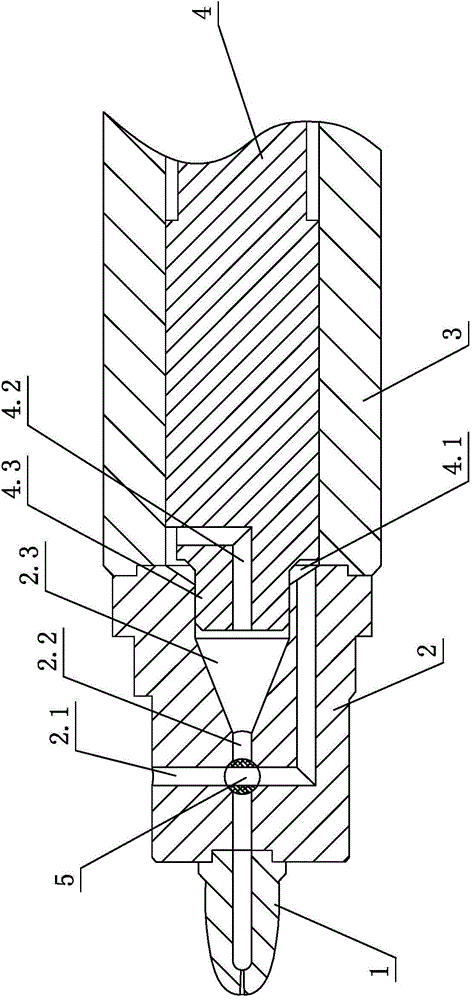
[0022] see figure 1 , the injection molding machine has no retention plunger injection storage cylinder structure, including the nozzle 1, the front flange 2 and the storage cylinder 3 which are sequentially sealed and assembled, and the plunger 4 inserted in the storage cylinder 3 which moves left and right; its characteristics In that: the front flange 2 is embedded with a shuttle valve 5; the plunger 4 is provided with a central channel 4.2; after injection, a material storage chamber 2.3 and a material storage chamber 2.3 are formed between the front flange 2 and the plunger 4 The annular material storage channel 4.1 conducts the raw material through the internal channel, and the residual rubber material is sent into the material storage chamber 2.3 to participate in the next glue injection, so as to achieve the purpose of cleaning the residual material.

[0023] Specifically, the front flange 2 is provided with a horizontal channel 2.2 and a vertical channel 2.1, which ar...

no. 2 example

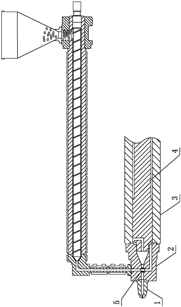
[0028] see Figure 4 , This injection molding machine has no retention plunger injection storage cylinder structure, which is different from the first embodiment in that: the shuttle valve 5 is spherical, has a passage across it, and has a rotating shaft extending outward on both sides. The front end flange 2 is a split type, and a spherical cavity and a shaft groove are correspondingly arranged at the junction, and the shuttle valve 5 is assembled together. This embodiment facilitates the repair or maintenance of the front flange 2 and the shuttle valve 5 .

[0029] Other parts not described are the same as those of the first embodiment, and will not be analyzed and described here.

no. 3 example

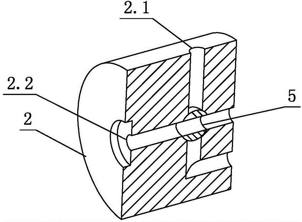
[0031] see Figure 5 , this injection molding machine has no retention plunger injection storage cylinder structure, which is different from the first embodiment in that: the vertical channel 2.1 is bent in the front flange 2, directly connected to the storage channel 4.1, and the horizontal channel 2.2 does not hand over, the shuttle valve 5 closes or opens the horizontal channel 2.2. The injection molding machine is in the material storage process, and the set program controls the rotation of the shuttle valve 5. When the passage in the shuttle valve 5 is completely separated from the horizontal passage 2.2, the horizontal passage 2.2 is closed, and the storage begins. It is helpful to prevent raw materials from overflowing from the horizontal passage 2.2 during the material storage process; at the same time, the distance of the vertical passage 2.1 is shortened, and the storage speed is fast.

[0032] Other parts not described are the same as those of the first embodiment,...


PUM


Abstract

The invention relates to a non-retention plunger injection storage cylinder structure of an injection moulding machine. The non-retention plunger injection storage cylinder structure comprises a spray nozzle, a front-end flange, a storage cylinder and a plunger, wherein the spray nozzle, the front-end flange and the storage cylinder are sequentially assembled hermetically; the plunger is inserted into the storage cylinder in a left-right moving way. The non-retention plunger injection storage cylinder structure is characterized in that a shuttle valve is embedded into the front-end flange; a central channel is arranged in the plunger; a storage cavity and an annular storage channel are formed between the front-end flange and the plunger after adhesive injection; a first-in first-out principle in a fused plastic storage process is realized by using an inner channel to transfer raw material; and residual material is pushed to the end opening of the front-end flange and injected into a mould in a storage process every time. According to the non-retention plunger injection storage cylinder structure, a series of problems caused by the retention of material at the front end of the plunger are completely prevented, the problems of difficult raw material replacement, plastic degradation and the like in a production process are ingeniously solved, so that the product waste is greatly reduced, the working efficiency and the finished product ratio are increased, and the difficulty of equipment maintenance work is lowered; residual adhesive material is conveyed into the storage cavity to participate in the adhesive injection, so that the purpose of removal of the residual material is reached.

Description

technical field [0001] The invention relates to a plunger injection structure of an injection molding machine, in particular to a non-retention plunger injection material storage cylinder structure of an injection molding machine. Background technique [0002] The plunger injection structure of the existing injection molding machine, because there is a certain gap and space between the plunger and the front flange, which cannot be completely eliminated, resulting in that the material at the front end cannot be completely ejected during injection, and the residual material at the front end of the plunger will be removed during the next material storage process. The rubber material is pushed back to the front end of the plunger again. This will cause the material retention at the front end of the plunger, making it difficult to clean the material. Long-term retention will cause plastic degradation. Regular equipment maintenance is required to ensure the quality of the product. ...

Claims


Application Information

Patent Timeline
Patent Type & Authority Applications(China)
IPC IPC(8): B29C45/02B29C45/54B29C45/17
CPCB29C45/542
Inventor 蒋小军卢嘉诚黄茂敬
Owner 广东伊之密精密注压科技有限公司
Why Eureka
Try Eureka