Energy-absorbing children automobile chair
A technology for children's cars and seats, applied in child seats, vehicle seats, vehicle parts, etc., can solve problems such as deformation of connection positions, increased discomfort of seat belts to children, and breakage, and achieve the effect of avoiding injuries.
- Summary
- Abstract
- Description
- Claims
- Application Information
AI Technical Summary
Problems solved by technology
Method used
Image

Examples
Embodiment 1
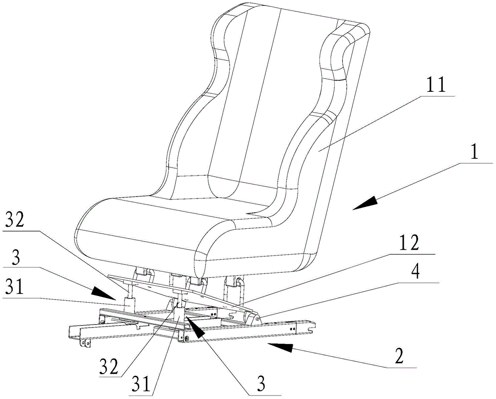
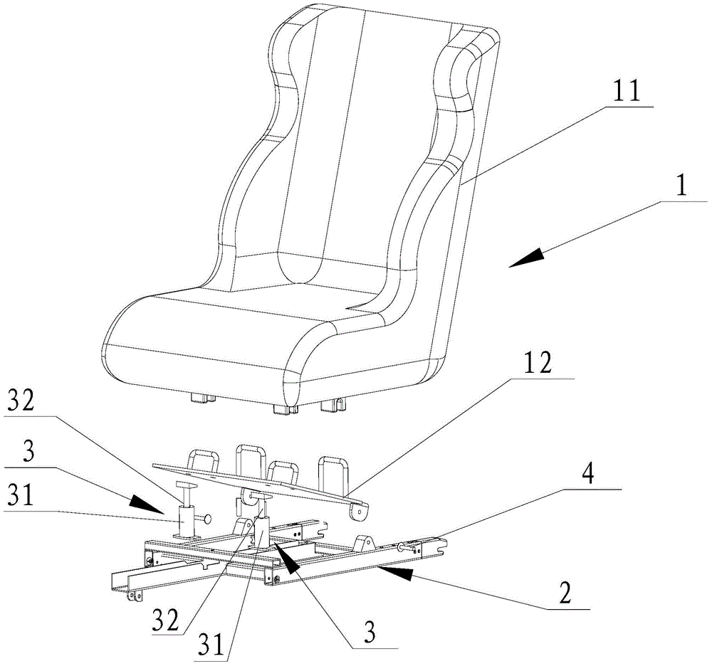
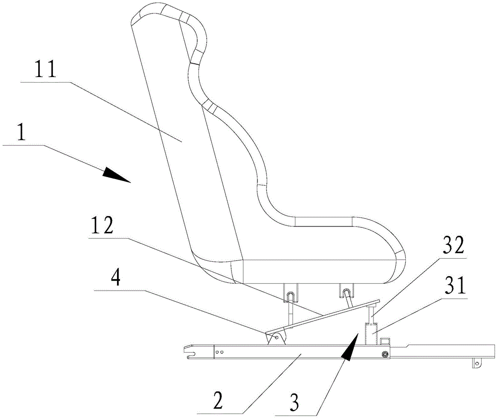
[0068] see Figure 1 to Figure 4 The child car seat shown includes a seat 1 and a base 2 arranged under the seat 1 and providing support for the seat 1 . The seat 1 has two opposite ends, one of which is rotatably connected to the base 2, and the other end is a movable end. In this embodiment, the rear end of the seat 1 is rotatably connected to the base 2 through a pin shaft 4, and the front end of the seat 1 is a movable end. Between the movable end of the seat 1 and the base 2, there is a telescopic cylinder 3 that can expand and contract along its own axial direction. The axis of the telescopic cylinder 3 is distributed along the up and down direction. The telescopic cylinder 3 is squeezed to expand and contract in the axial direction to provide the cushioning force of the seat 1 . The telescopic cylinder 3 can be a hydraulic cylinder or an air cylinder.
[0069] In this embodiment, the seat 1 includes a seat body 11 and a frame 12 detachably connected to the bottom...
Embodiment 2
[0074] see Figure 5 The child car seat shown is basically similar in structure to that of Embodiment 1, the only difference being that the seat 1 does not adopt a split structure, but an integral structure, that is, the frame 12 on the seat 1 and the The seat body 11 is provided integrally. The working principle of this embodiment is the same as that of Embodiment 1, and will not be repeated here.
[0075]
Embodiment 3
[0077] see Figure 6 to Figure 11 The child car seat shown includes a seat 1 and a base 2 arranged under the seat 1 and providing support for the seat 1 . The seat 1 includes a seat body 11 and a frame 12 detachably connected to the bottom of the seat body 11 .
[0078] The seat 1 is slidably arranged on the base 2 along the front-to-back direction. The base 2 has a slide rail 22 for providing sliding support for the seat 1. The slide rail 22 extends along the horizontal front-rear direction. Here, the slide rail 22 is provided with two , on the left and right sides, respectively. Both left and right sides of the frame 12 have sliding blocks 14 , and the sliding blocks 14 are slidably arranged on the sliding rail 22 along the extending direction of the sliding rail 22 .
[0079] The frame 12 has a crossbeam 13 connected between the slide rails 22 on both sides, and the base 2 has a stopper 21, which is a crossbar connected between the slide rails 22 on both sides, and ...
PUM
 Abstract
Description
Claims
Application Information