
Methods and systems for oxygen sensors

An oxygen sensor and sensor technology, applied in the direction of charging system, machine/engine, electrical control, etc., can solve the problems of sensor accuracy measurement and/or control reduction, confusion of sensor measurement values, etc.

Active Publication Date: 2018-10-16
FORD GLOBAL TECH LLC
View PDF5 Cites 0 Cited by
  • Summary
  • Abstract
  • Description
  • Claims
  • Application Information

AI Technical Summary

Problems solved by technology

As a result, various sensitivities may confound sensor measurements, and the accuracy of the sensors and thus the measurement and / or control of EGR may be degraded

Method used


Image

  • Methods and systems for oxygen sensors
  • Methods and systems for oxygen sensors
  • Methods and systems for oxygen sensors

Examples


Embodiment Construction

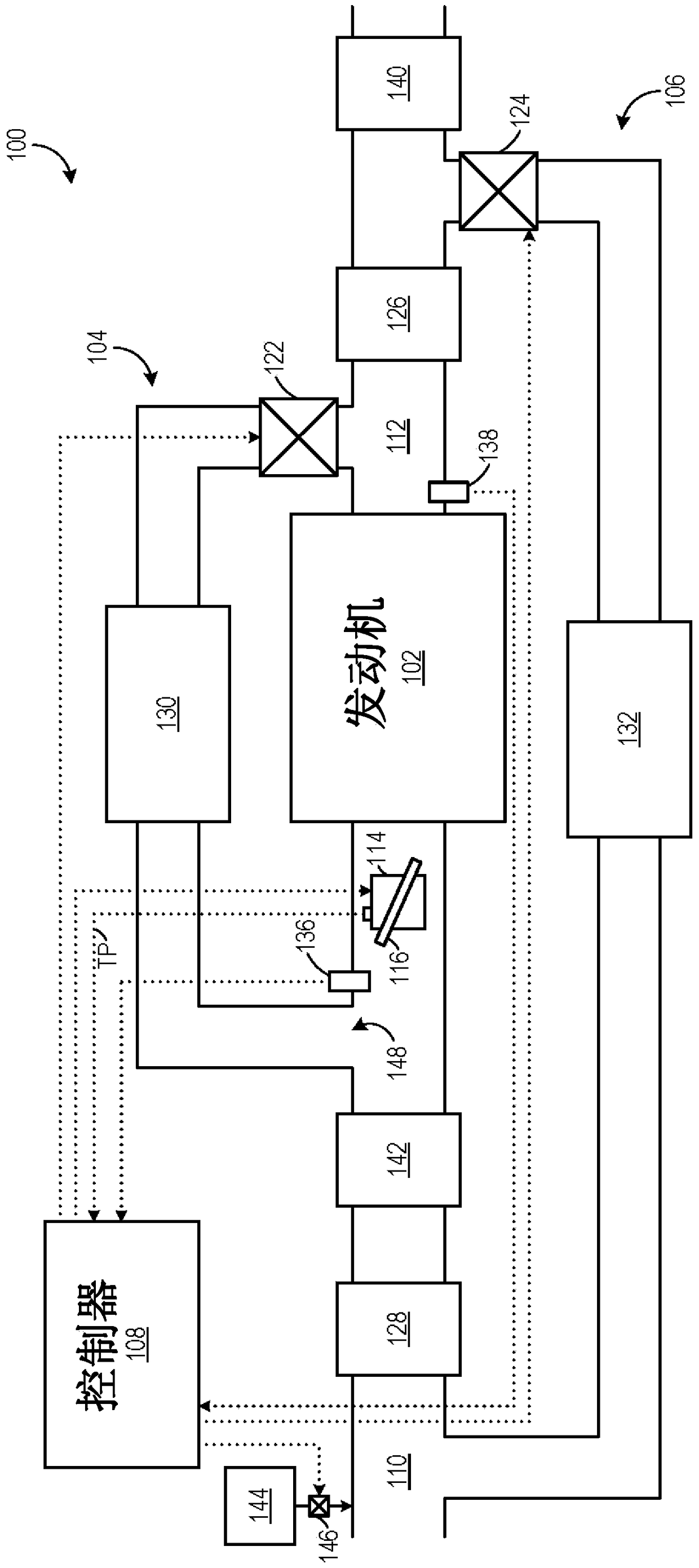
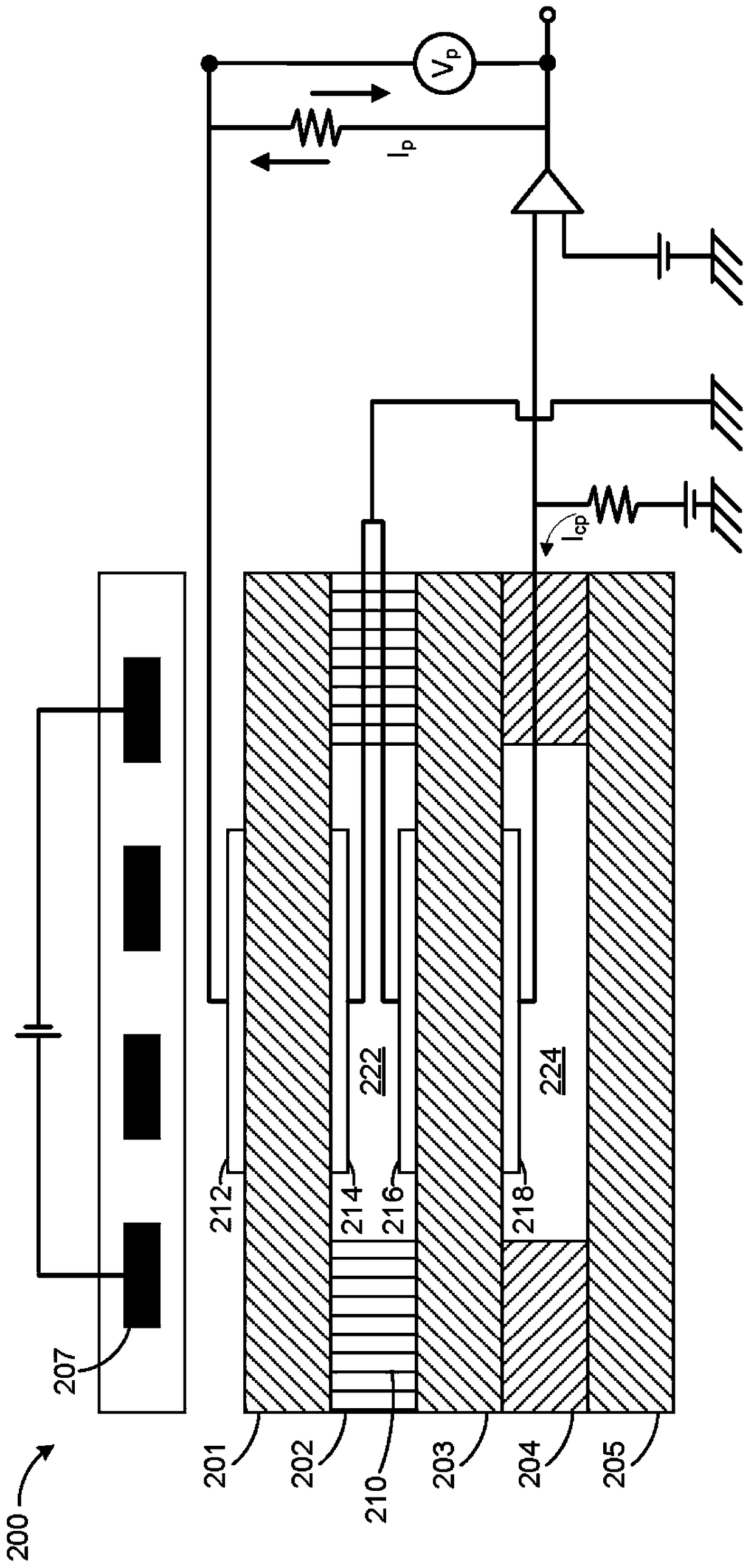
[0010] The following description relates to methods and systems for an engine system having an exhaust gas recirculation (EGR) system and catalytic and non-catalytic intake air composition sensors, such as oxygen sensors. In one example, a method includes indicating an intake oxygen concentration and a fuel vapor concentration based on an output from a catalytic sensor and an output from a non-catalytic sensor. The method further includes adjusting EGR in response to the oxygen concentration, and adjusting fuel injection and / or fuel vapor purge in response to the fuel vapor concentration. In such an example, the non-catalytic sensor output may be indicative of oxygen concentration, while the difference between the catalytic sensor output and the non-catalytic sensor output may be indicative of fuel vapor concentration. Accordingly, a measurement of EGR may be obtained that is not affected by the presence of fuel vapors in the engine intake. Accordingly, EGR may be controlled ...


PUM


Abstract

The present invention relates to methods and systems for oxygen sensors. Various systems and methods are described for an engine system having an exhaust gas recirculation system and catalytic and non-catalytic intake oxygen sensors. In one example, the catalytic oxygen sensor is used to measure and control exhaust gas recirculation while measuring and controlling fuel vapor purge based on the catalytic and non-catalytic sensors.

Description

technical field [0001] The present application generally relates to a gas composition sensor included in an intake system of an internal combustion engine. Background technique [0002] Engine systems may utilize recirculation of exhaust gas from the engine exhaust system to the engine intake system (intake port), a process known as exhaust gas recirculation (EGR), to reduce regulated emissions. EGR systems may include various sensors to measure and / or control EGR. As one example, an EGR system may include an intake air composition sensor, such as an oxygen sensor, that may be used to measure oxygen to determine the proportion of combustion gases in the engine intake. Additionally, the sensor is sensitive to total pressure. Therefore, the sensor can be sensitive to diluents such as ambient humidity, exhaust humidity and carbon dioxide. Oxygen sensors are sensitive to both oxygen partial pressure and the presence of fuel (or other reducing and oxidizing agents) due to the ...

Claims


Application Information

Patent Timeline
Patent Type & Authority Patents(China)
IPC IPC(8): F02D41/30F02D21/08F02D43/00F02D41/00F02M25/08
CPCF02D41/144F02D41/1441F02D41/1456F02D41/0032F02D41/0052Y02T10/40F02D41/1454F02D41/1455F02D41/3005
Inventor R·D·珀西富尔
Owner FORD GLOBAL TECH LLC
Learn More