Check patentability & draft patents in minutes with Patsnap Eureka AI!

Improved Power Cell Bypass Method And Apparatus For Multilevel Inverter

A technology of electric power and electric power conversion, which is applied in the output power conversion device, electrical components, and the direction of the non-reversible DC power input to AC power output.

Inactive Publication Date: 2014-09-24
ROCKWELL AUTOMATION TECH
View PDF5 Cites 1 Cited by
  • Summary
  • Abstract
  • Description
  • Claims
  • Application Information

AI Technical Summary

Problems solved by technology

However, particularly since the stages are connected in series with each other, device degradation within a particular power stage may inhibit the ability to provide the desired output voltage to the load

Method used


Image

  • Improved Power Cell Bypass Method And Apparatus For Multilevel Inverter
  • Improved Power Cell Bypass Method And Apparatus For Multilevel Inverter
  • Improved Power Cell Bypass Method And Apparatus For Multilevel Inverter

Examples


Embodiment Construction

[0012] Referring now to the drawings, in which like reference numerals are used to refer to like elements throughout and wherein the various features are not necessarily drawn to scale, there are described below several embodiments or implementations in conjunction with the drawings.

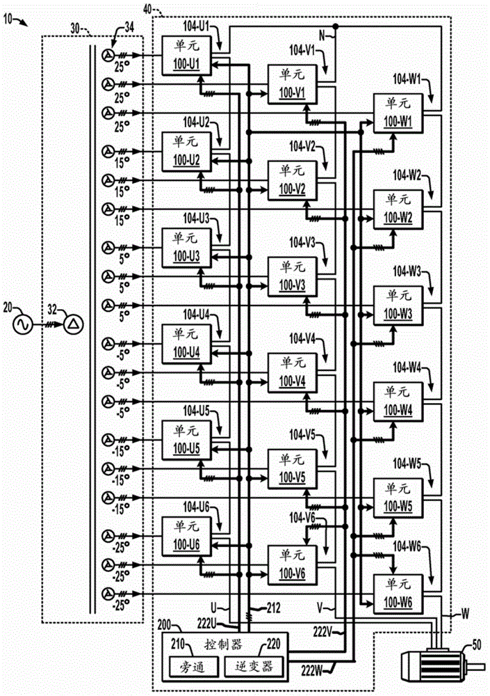
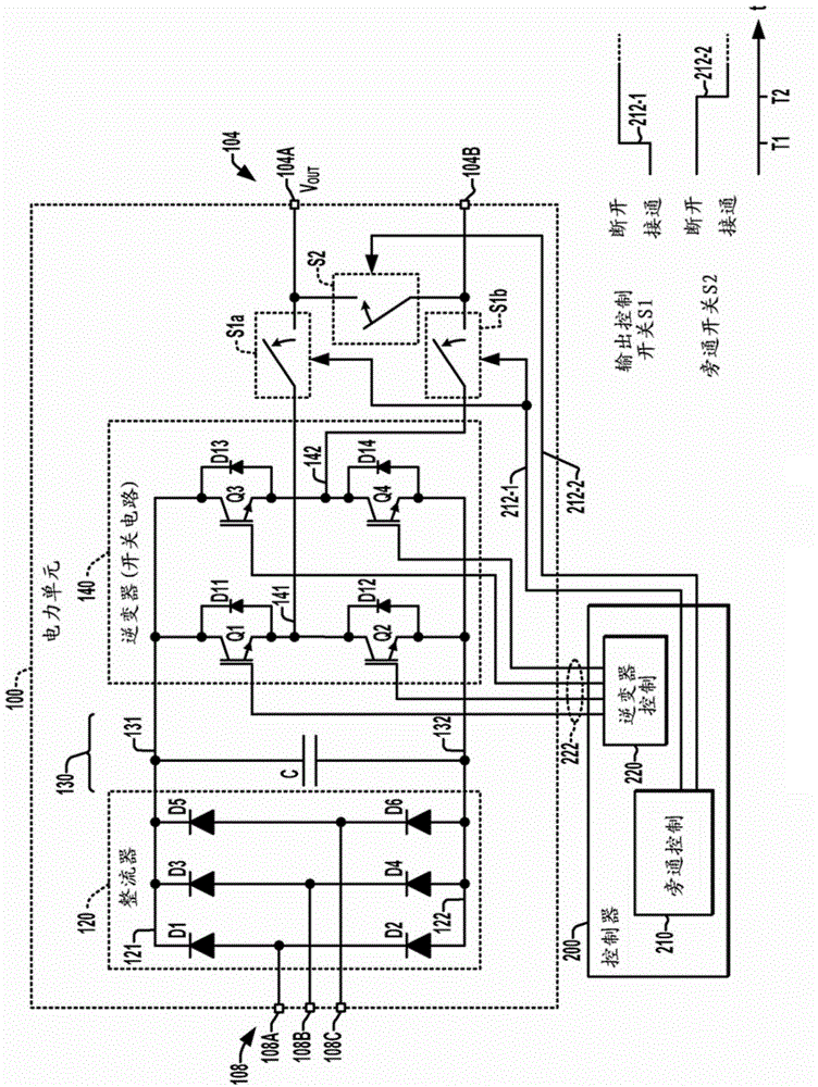
[0013] figure 1 An exemplary multi-level inverter motor drive power conversion system 10 is shown comprising, for each of the three sections associated with motor phases U, V, and W of a motor load 50, the system 10 comprising power stages with series connections 100-1, 100-2, 100-3, 100-4, 100-5, 100-6 three-phase multilevel inverter 40. Other implementations of driving other forms of load 50 are possible, where the present disclosure is not limited to motor-driven power converters. In some embodiments, each power stage 100 includes a switching device (eg, the following figure 2 Q1 to Q4 in the H-bridge switching circuit or inverter 140, although any suitable form of switching circuit 140 ma...


PUM


Abstract

Multilevel inverters, power cells and bypass methods are presented in which a power cell switching circuit is selectively disconnected from the power cell output, and a bypass which is closed to connect first and second cell output terminals to selectively bypass a power stage of a multilevel inverter, with an optional AC input switch to selectively disconnect the AC input from the power cell switching circuit during bypass.

Description

technical field [0001] The present disclosure relates to the technical field of power conversion, and more particularly relates to a power unit bypass method and device for a multi-level inverter. Background technique [0002] Multilevel inverters are sometimes used in motor drives and other power conversion applications to generate high voltage drive signals and provide them to motors or other loads in high power applications. One form of multilevel inverter is a cascaded H-bridge (CHB) inverter architecture employing multiple series-connected power stages, such as an H-bridge inverter used to drive each motor winding phase. Each H-bridge is powered by a separate DC source and driven by a switching signal to generate a positive or negative output voltage. The series combination of multiple H-bridge stages provides the multi-level inverter output capability for driving the load. However, particularly since the stages are connected in series with each other, device degradati...

Claims


Application Information

Patent Timeline
Patent Type & Authority Applications(China)
IPC IPC(8): H02M7/00
CPCH02M7/49H02M5/458H02M2001/325H02M1/325
Inventor 韦立祥肖原卢海辉道格拉斯·B·韦伯
Owner ROCKWELL AUTOMATION TECH
Features
  • R&D
  • Intellectual Property
  • Life Sciences
  • Materials
  • Tech Scout
  • Unparalleled Data Quality
  • Higher Quality Content
  • 60% Fewer Hallucinations
Learn More