
Multi-position hole saw assembly with plug ejector

A technology for assemblies and blockages, which is applied in the direction of drilling tool accessories, tool workpiece connection, boring machine/drilling machine parts, etc., can solve problems such as difficult removal of blockages, and achieve the effect of reducing the number

Inactive Publication Date: 2014-09-24
FOEVLING TRAEBYG
View PDF8 Cites 3 Cited by
  • Summary
  • Abstract
  • Description
  • Claims
  • Application Information

AI Technical Summary

Problems solved by technology

[0005] Another known problem is that after the hole is made, it can be difficult to remove the blockage of sawn material from the hole saw

Method used


Image

  • Multi-position hole saw assembly with plug ejector
  • Multi-position hole saw assembly with plug ejector
  • Multi-position hole saw assembly with plug ejector

Examples


Embodiment Construction

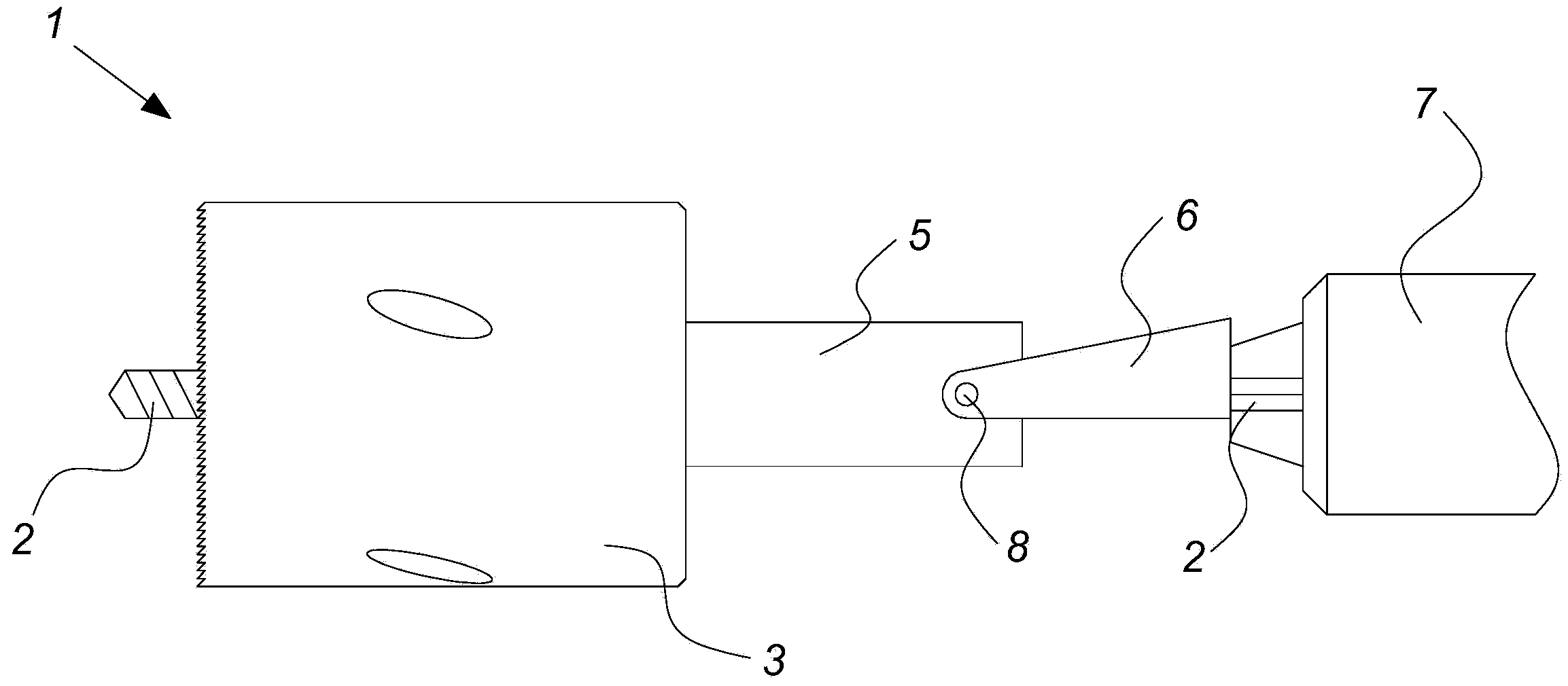
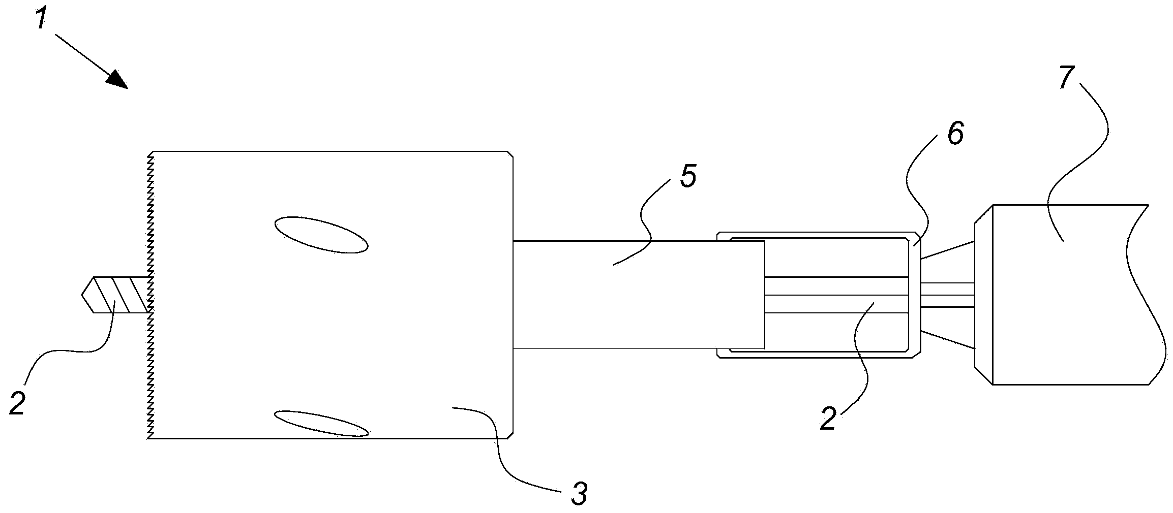
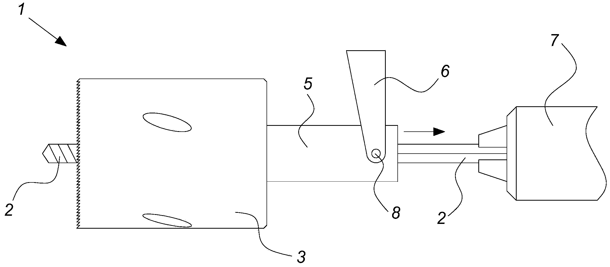
[0061] Figures 1a-2b are different side views of a hole saw assembly 1 according to an embodiment of the invention, the hole saw assembly 1 being arranged in two different ways.

[0062] The hole saw assembly 1 illustrated in these figures comprises a circular saw blade 3 firmly mounted and secured to a mount 5 , and a through center drill 2 having a tool end and a machining end. The circular saw blade 3 is configured such that its axis of rotation coincides with the axis of rotation passing through the center drill 2 .

[0063] Through the central drill 2 a drill 2 is formed at its tool end, slightly protruding from the plane defined by the cutting edge of the circular saw blade 3 . This means that the drill 2 can drill into the material at the center point of the hole to be drilled and that the drill 2 can be used as a guide for the actual sawing of the circular saw blade 3 . On the other hand, the through center drill 2 has a hexagonal sectional shape at its other end, s...


PUM


Abstract

A hole saw assembly is disclosed comprising an elongated arbor, a mounting piece arranged around the arbor and rotationally locked to the arbor but slidable over the arbor, a circular saw blade mounted on the mounting piece, the rotational axis of the circular saw blade coinciding with the longitudinal axis of the arbor, a central drill extending along the rotational axis of the circular saw blade and being rotationally and axially fixed to the arbor, means for releasably fixating the mounting piece in relation to the arbor at one or more positions along the arbor and a plug ejector for ejecting a plug of sawn material from the interior of the circular saw blade by sliding the mounting piece and the circular saw blade in relation to the central drill and for working as a stop for the sliding of the mounting piece towards the tool end of the arbor.

Description

technical field [0001] The present invention relates to a hole saw, and more particularly to a rotary hole saw for use with a power tool or a hand-held drill. Background technique [0002] When using a conventional rotary hole saw of the circular saw blade around a center drill type, the distance that the center drill protrudes from the plane defined by the cutting edge of the saw blade can be significant in some cases. [0003] If the center drill protrudes too much, the drill may cause damage to electrical fittings, water pipes, or other hidden structures behind the board that is being drilled, before the saw blade cuts through the board. [0004] On the other hand, if the protrusion of the center drill is too short, and the hole will be made at the junction between two slanted panels (such as known types of ceilings), the center drill may not be able to grip the board and the circular saw blade The saw cut acts as a guide, which is what this type of hole saw is for. [...

Claims


Application Information

Patent Timeline
Patent Type & Authority Applications(China)
IPC IPC(8): B23B51/04
CPCB23B51/0426B23B2251/60B23B2260/004B23B51/0473B23B51/0453Y10T408/51B23B2251/428B23B2240/00B23B51/044
Inventor 俄林·维乌夫
Owner FOEVLING TRAEBYG
Learn More