Device for positioning an electronic test head with respect to a manipulator for manipulating electronic components, in particular integrated circuits

a technology for manipulators and electronic components, applied in the direction of electronic circuit testing, measurement devices, instruments, etc., can solve the problems of slow positioning of electronic test heads, difficult to manufacture and assemble, and high production costs, so as to improve the quality of electronic components. , the effect of simple design

Active Publication Date: 2005-11-22
SPEA
View PDF3 Cites 4 Cited by
  • Summary
  • Abstract
  • Description
  • Claims
  • Application Information

AI Technical Summary

Benefits of technology

[0004]It is an object of the present invention to provide a device for positioning an electronic test head with respect to an electronic component manipulator, designed to eliminate the aforementioned drawbacks of the known art, and which, in particular, permits accurate, fast, easy positioning of the electronic head, while at the same time being relatively cheap and easy to produce as a whole.
[0006]The device according to the invention permits extremely fast, easy positioning of the electronic head, by requiring of the operator, as will be seen, only a small number of operations which are much easier to perform as compared with those of the known devices described above. Moreover, as compared with known solutions, the device according to the invention comprises fewer moving parts, and is therefore simpler in design and cheaper and easier to produce as a whole.

Problems solved by technology

In particular, positioning the electronic test head is a slow, painstaking job, by the operator having to work on a number of separate moving components and respective lock lever mechanisms.
Moreover, the positioning assembly comprises a large number of moving components, and is therefore fairly complex and expensive to produce and assemble.

Method used


Image

  • Device for positioning an electronic test head with respect to a manipulator for manipulating electronic components, in particular integrated circuits
  • Device for positioning an electronic test head with respect to a manipulator for manipulating electronic components, in particular integrated circuits
  • Device for positioning an electronic test head with respect to a manipulator for manipulating electronic components, in particular integrated circuits

Examples


Embodiment Construction

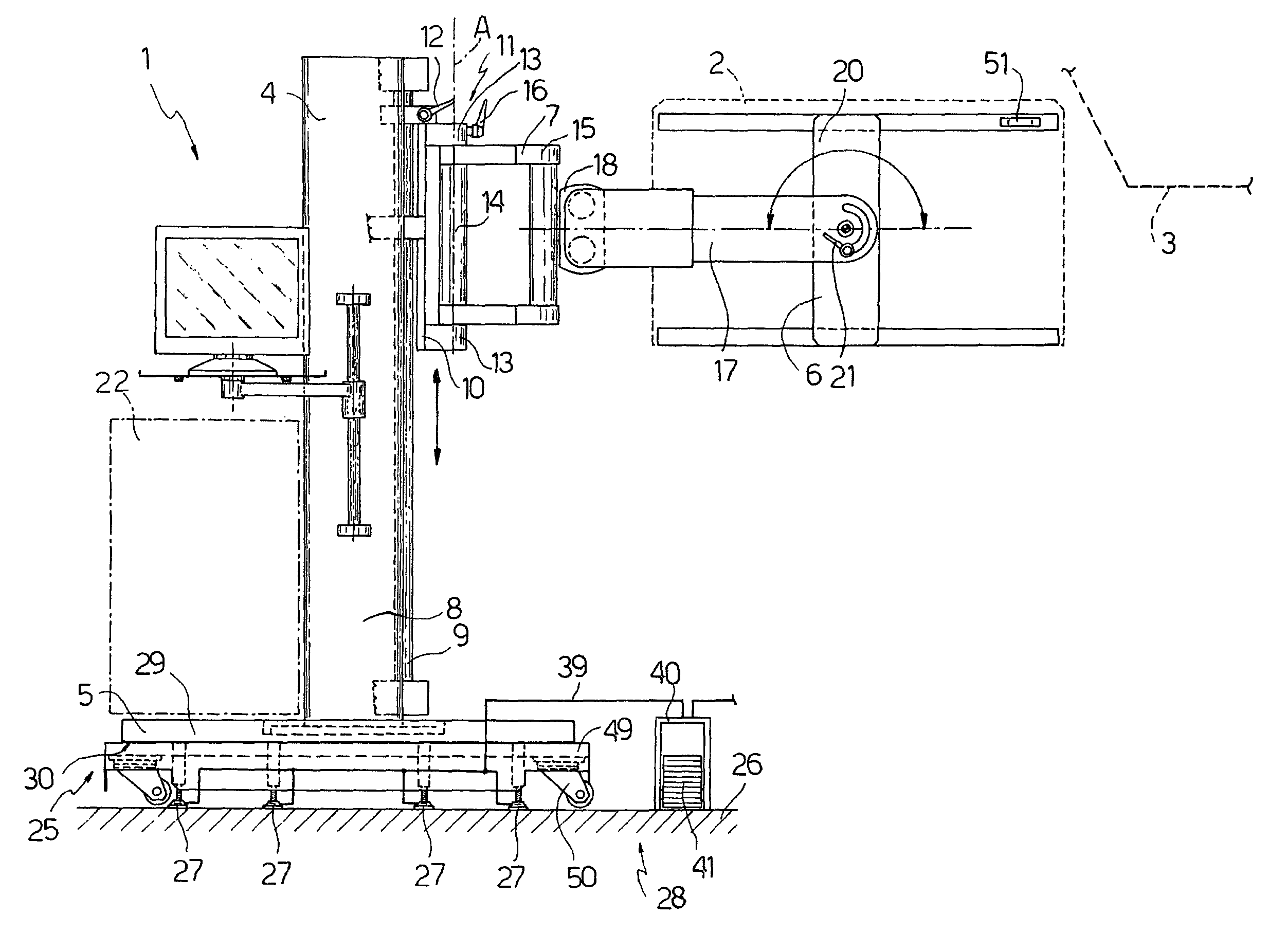
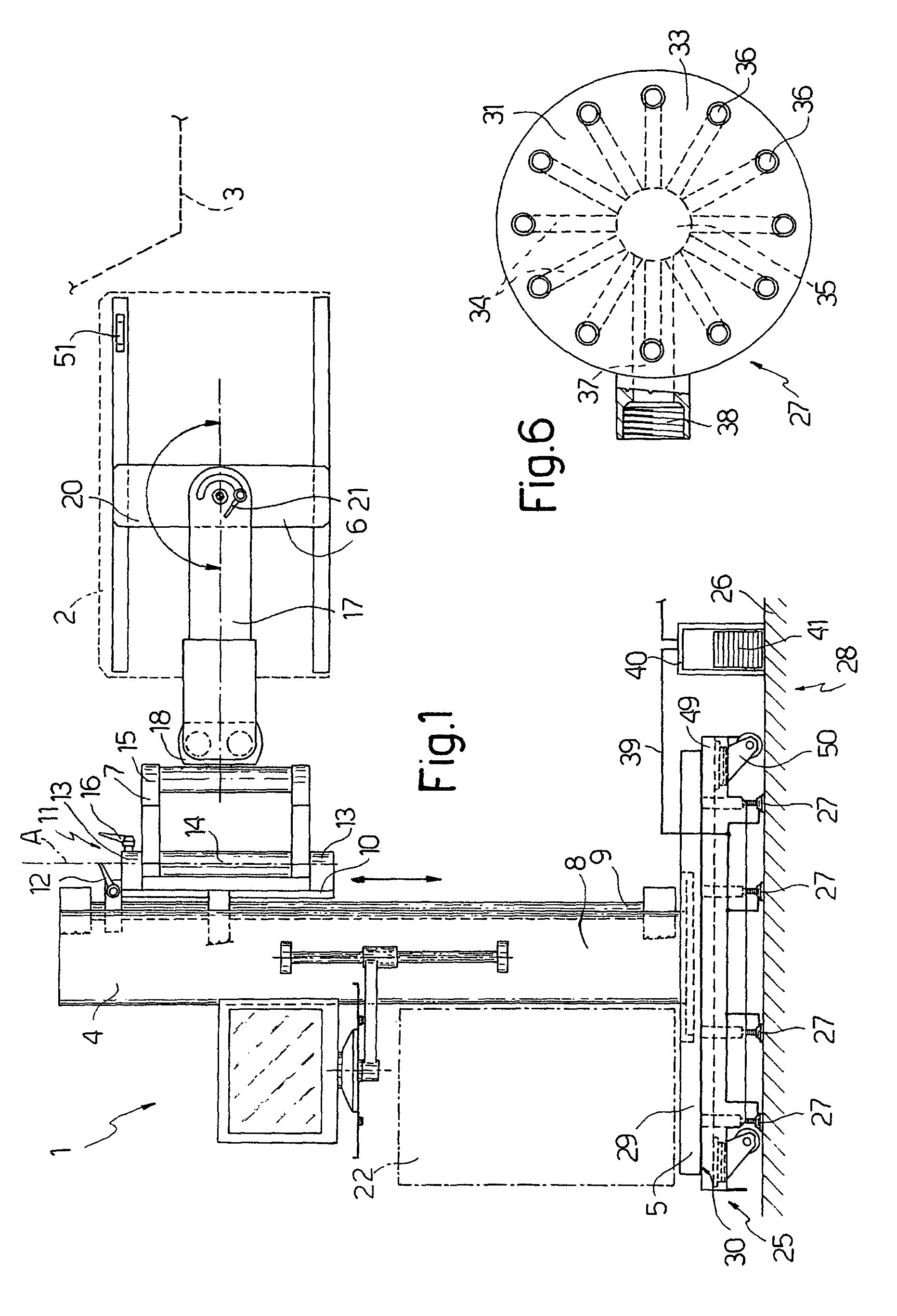
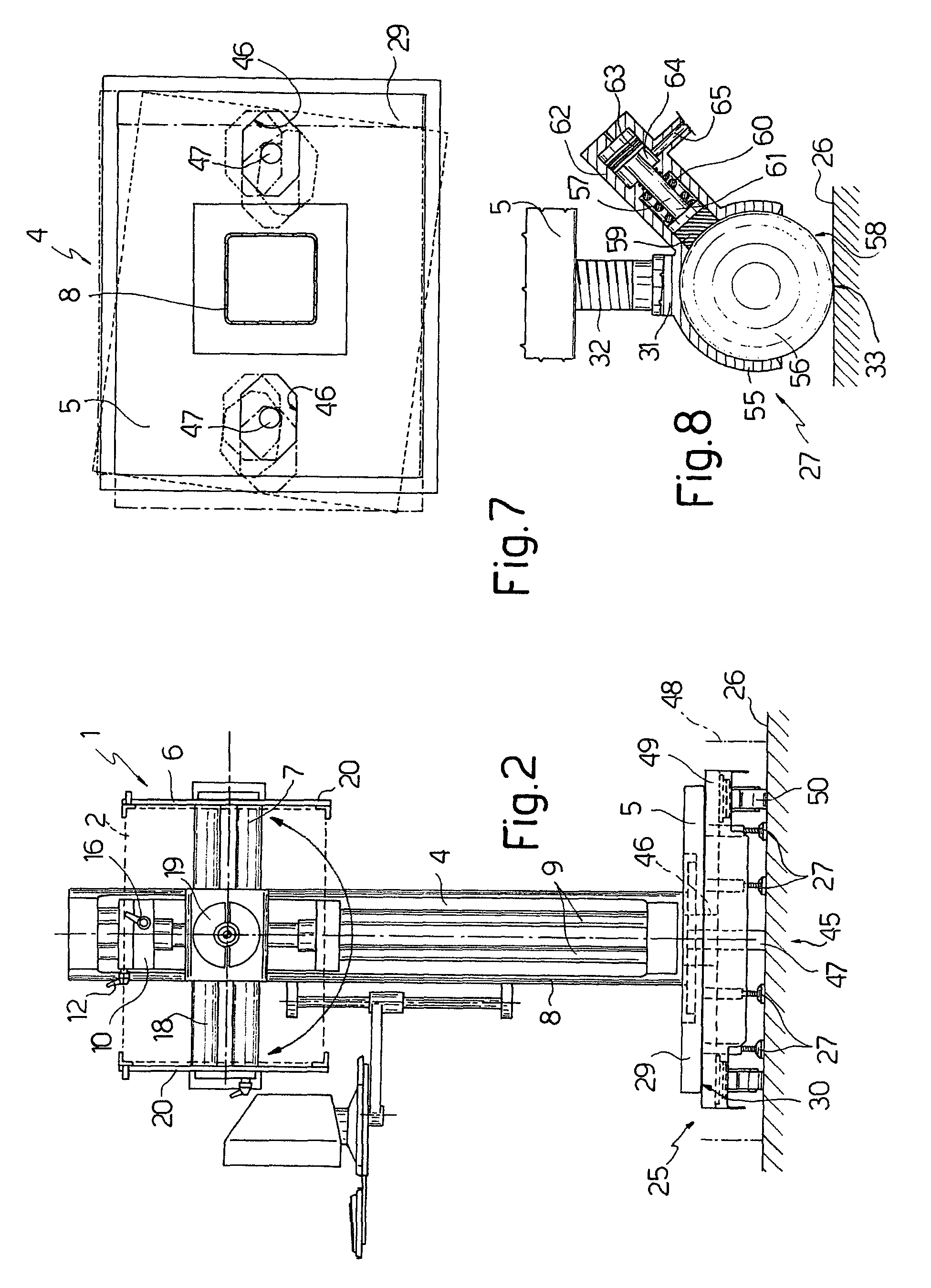
[0014]Number 1 in FIGS. 1 to 3 indicates as a whole a device for positioning an electronic test head 2 (known and only shown schematically by a dash line) with respect to a manipulator 3 (also known and only shown by a dash line in FIG. 1) for manipulating electronic components, in particular integrated circuits.

[0015]Device 1 comprises a supporting structure 4 fitted to a base 5; a frame 6 to which electronic head 2 is connectable; and an actuating assembly 7 for moving frame 6 with respect to supporting structure 4.

[0016]Supporting structure 4 comprises a vertical column 8 fixed to base 5 and having two parallel, vertical, cylindrical guides 9; actuating assembly 7 comprises a slide 10 mounted to run along guides 9, and an arm mechanism 11 fitted integrally to slide 10; and a known releasable lock lever mechanism 12 is associated with slide 10 to lock slide 10 in a predetermined position with respect to column 8.

[0017]Arm mechanism 11 comprises two end supports 13, between which e...


PUM


Abstract

A device for positioning an electronic test head with respect to a manipulator for manipulating electronic components, in particular integrated circuits, includes a supporting structure fitted to a base, a frame to which the electronic head is connectable, and an actuating assembly for moving the frame with respect to the supporting structure; the base has a number of shoes, e.g. compressed-air shoes, cooperating with a supporting surface; when idle, the base rests on the supporting surface by means of the shoes; when compressed air is supplied to the shoes, the shoes are raised vertically by a few microns with respect to the supporting surface; in which condition, the device is supported hydrostatically and substantially weightlessly with respect to the supporting surface, and the whole device can easily be moved manually by the operator in any direction parallel to the supporting surface.

Description

[0001]The present invention relates to a device for positioning an electronic test head with respect to a manipulator for manipulating electronic components, in particular integrated circuits.BACKGROUND OF THE INVENTION[0002]Automatic testing of integrated circuits and other electronic components is performed using devices of the type illustrated, for example, in European Patent Application EP-A-0102217, which comprises a fixed supporting structure fitted with a positioning assembly in turn fitted with an electronic test head. The positioning assembly slides vertically with respect to the supporting structure, and can also be extended horizontally in an accordion-like movement along three parallel axes to position the electronic head correctly with respect to the test component or circuit carried by a manipulator. Each moving component of the positioning assembly has a lock lever mechanism, and the electronic test head is positioned manually by an operator working separately on each...

Claims


Application Information

Patent Timeline
Patent Type & Authority Patents(United States)
IPC IPC(8): G01R31/28
CPCG01R31/2887
Inventor BONARIA, LUCIANO
Owner SPEA
Why Eureka
Try Eureka