Latch for a vehicle

a technology for latching and vehicles, applied in the field of latching, can solve the problems of affecting the safety of passengers in vehicles, requiring high cost and/or heavyness, and system incorporating several features, etc., and achieves the effects of convenient and fast assembly, easy and cheap production, and simple closure mechanism

Inactive Publication Date: 2006-11-30
MERITOR TECH
View PDF9 Cites 27 Cited by
  • Summary
  • Abstract
  • Description
  • Claims
  • Application Information

AI Technical Summary

Benefits of technology

[0010] The present invention provides a simpler closure mechanism that is easier and cheaper to produce and quicker to assemble.

Problems solved by technology

If the pawl becomes disengaged from the claw during an accident, the door can open, thereby possibly endangering the occupants of the vehicle.
Therefore, they are necessarily expensive and / or heavy.
This system incorporates several features (link, rotatable lug, lever and associated pivots), all of which are costly.
The serpentine guide tracks of U.S. Pat. No. 5,564,761 and U.S. Pat. No. 5,288,115 are complicated and expensive to produce, not least because they must be sufficiently strong to withstand the various closure loads applied to them.

Method used


Image

  • Latch for a vehicle
  • Latch for a vehicle
  • Latch for a vehicle

Examples


Embodiment Construction

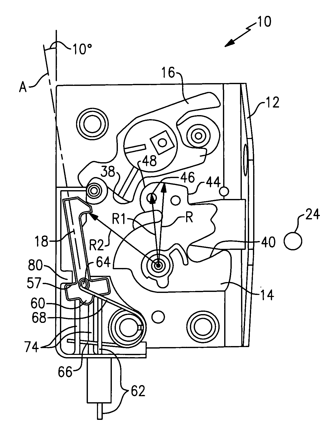
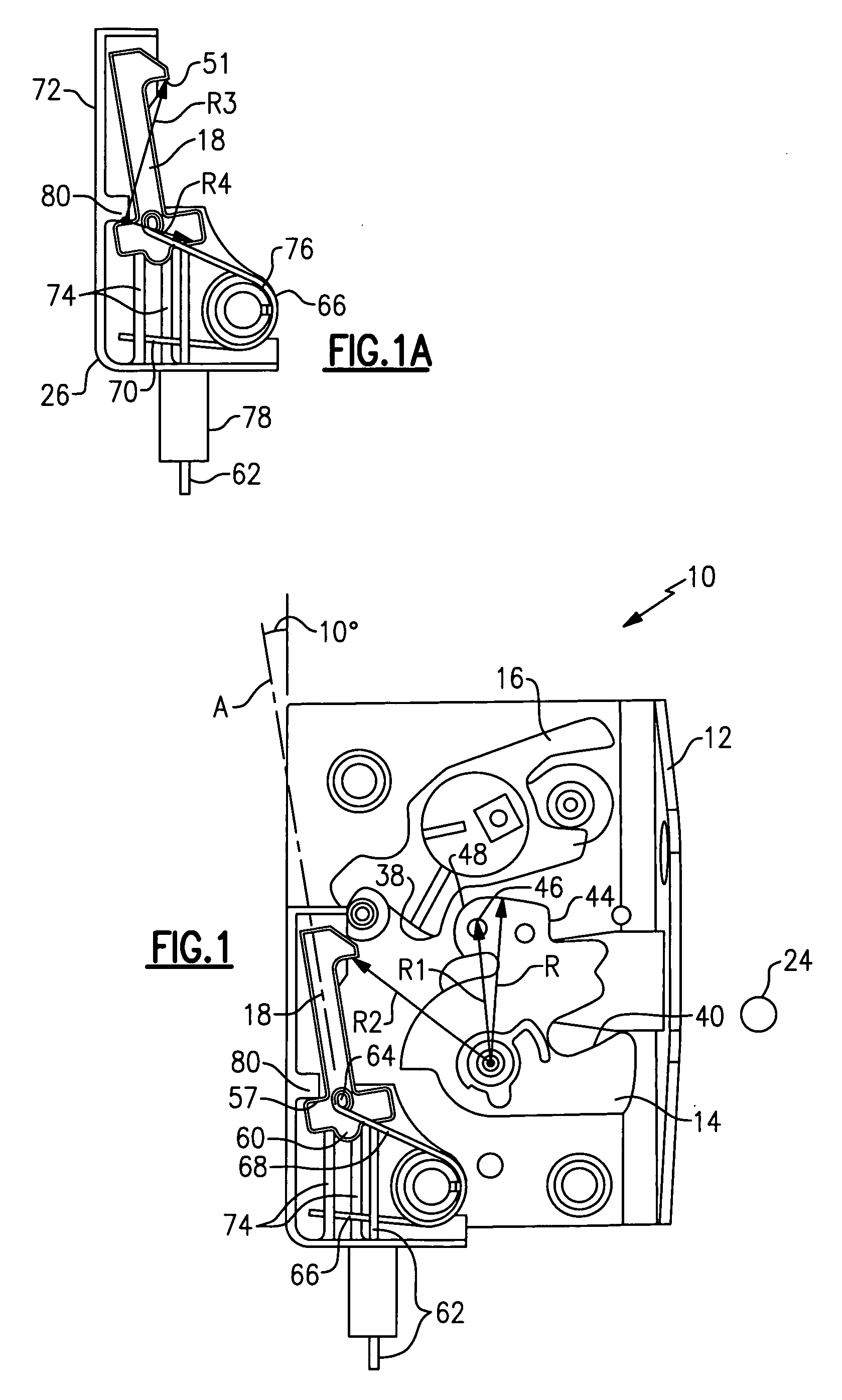
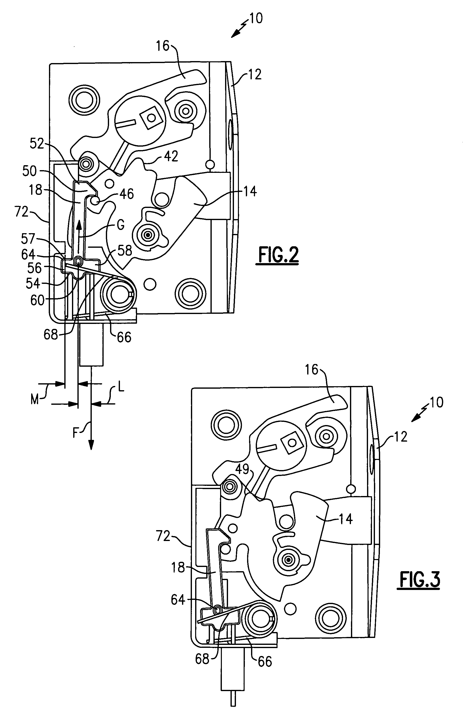
[0022] As shown in FIG. 5, a latch assembly 10 includes a latch chassis 12, a latch bolt in the form of a rotating claw 14, a pawl 16, a closure element 18, a transmission path 20 and an actuator 22.

[0023] The chassis 12 is a retention plate made of metal, such as steel, for example. Holes 30 enable the fully assembled latch assembly 10 to be secured to an associated door. The chassis 12 includes a mouth 32 for receiving a striker 24 (shown in FIG. 1). The claw 14 rotates about a claw pivot 34 mounted on the chassis 12, and the pawl 16 rotates about a pawl pivot 36 mounted on the chassis 12.

[0024] As shown in FIG. 1, the pawl 16 includes a pawl tooth 38. The claw 14 includes a claw mouth 40 for receiving the striker 24, a closed abutment 42 (shown in FIG. 2) and a first safety abutment 44. The rotating claw 14 also includes a power closure abutment in the form of an upstanding pin 46.

[0025] As shown in FIG. 2, the closure element 18 is generally elongate and includes a first end ...


PUM


Abstract

A latch assembly includes a latch bolt having a power closure abutment, a first safety abutment and a closed abutment that is moveable between an open position, a first safety position and a closed position. The latch assembly includes a pawl including a pawl tooth having an engaged position defined by engagement between the pawl tooth and one of the first safety abutment and the closed abutment at which the pawl releaseably retains the latch bolt in one of the first safety position and the closed position, respectively, and a released position in which the latch bolt is free to move to the open position. The latch assembly also includes a closure element having a first abutment and a second abutment. The first abutment is releaseably engageable with the closure abutment. The closure element has a first position at which the closure element is disengaged from the closure abutment, a second position at which the first abutment of the closure element is engaged with the closure abutment and the latch bolt is in the first safety position, and a third position at which the first abutment of the closure element is engaged with the closure abutment and the latch bolt is in the closed position. When the closure element is in the first position and the latch bolt is in the first safety position, actuation of a power actuator causes the closure element to move through the second position to the third position, thereby closing the latch. During movement of the closure elements from the second position into the third position, the closure abutment is positioned generally between the first abutment and the second abutment.

Description

REFERENCE TO RELATED APPLICATION [0001] This application claims priority to United Kingdom Application GB 0509350.5 filed on May 7, 2005. BACKGROUND OF THE INVENTION [0002] The present invention relates generally to a latch, in particular a latch for a passenger door or driver door of a land vehicle, such as an automobile. [0003] Latches which enable vehicle doors are known, in particular car doors that are to be held in a closed position. Such known latches also allow the door to be held in a first safety position, i.e., a position at which the door will not open, but which nevertheless is not a fully closed position. [0004] Some vehicle door latches incorporate a power closure system wherein the door is manually closed to the first safety position. A power actuator, typically an electric motor, closes the door from the first safety position to the fully closed position. Such a latch is shown in U.S. Pat. No. 4,892,339. In this case, a rotating claw is engaged at a peripheral edge ...

Claims


Application Information

Patent Timeline
Patent Type & Authority Applications(United States)
IPC IPC(8): E05C3/06E05B65/12E05B65/32
CPCE05B77/04E05B85/243E05B81/20Y10T292/1047
Inventor SPURR, NIGEL
Owner MERITOR TECH
Why Eureka
Try Eureka