Method and device for generating a liquid mist

a technology of liquid mist and atomiser, which is applied in the direction of weather influence devices, offensive equipment, combustion processes, etc., can solve the problems of increasing the risk of discovery, difficult to discover by ir measurement and radar, and the prior-art technique of generating mist through atomiser nozzles, etc., and achieves high water pressure and simple devices

Inactive Publication Date: 2006-04-25
FORSVARETS MATERIELVERK
View PDF14 Cites 3 Cited by
  • Summary
  • Abstract
  • Description
  • Claims
  • Application Information

AI Technical Summary

Benefits of technology

[0009]The object of the present invention is to generate and spread mist in a more efficient way and to design a simpler device than before. A further object is to provide droplets without using space-requiring and heavy installations to produce high water pressures.

Problems solved by technology

If an object is covered by water mist, it will be difficult to discover by IR measurement and radar.
A drawback of intermittent spreading of mist is that there is a risk that a first layer of mist has time to drift away before the next layer has been positioned, which increases the risk of discovery.
Prior-art technique of generating mist by means of atomiser nozzles, however, suffers from several deficiencies.
It takes quite a long time to produce a complete mist, thus requiring a long forewarning time in case of an attack by, for example, homing missiles.
A mist intended to make an object invisible to an IR homing device gives poor protection against a radar homing device and vice versa.
Therefore at least two types of atomiser nozzles are frequently used, one generating an IR mist and one generating a radar mist: a method requiring much space and making the device expensive.
Moreover the device requires a water pressure of 250–300 bar to produce the desired size of droplets, which results not only in a high water and power consumption but also places great demands on pipes, connections and the like.
In cold weather, there is also a risk of the atomiser nozzles being clogged by ice and the protected object being covered with ice.
There is also a risk that the atomiser nozzles are clogged by dirt particles, especially in cases where the water used is lake water or sea water.
Moreover, atomiser nozzles are poor at spreading the generated mist, which makes it necessary to use a plurality of nozzles to generate a sufficient layer of mist also for a small object.
All in all, this results in a mist-generating device having a high water and power consumption and including a great number of large and heavy components.

Method used


Image

  • Method and device for generating a liquid mist
  • Method and device for generating a liquid mist
  • Method and device for generating a liquid mist

Examples


Embodiment Construction

[0019]Further scope of applicability of the present invention will become apparent from the detailed description given hereinafter. However, it should be understood that the detailed description and specific examples, while indicating preferred embodiments of the invention, are given by way of illustration only, since various changes and modifications within the spirit and scope of the invention will become apparent to those skilled in the art from this detailed description.

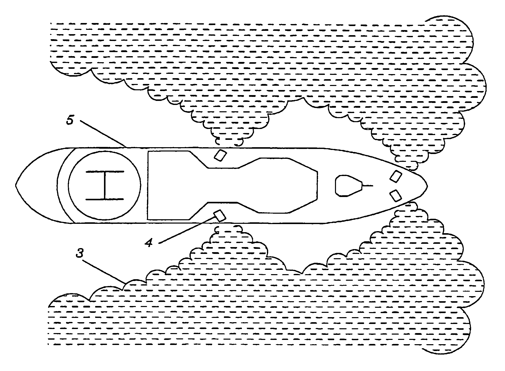
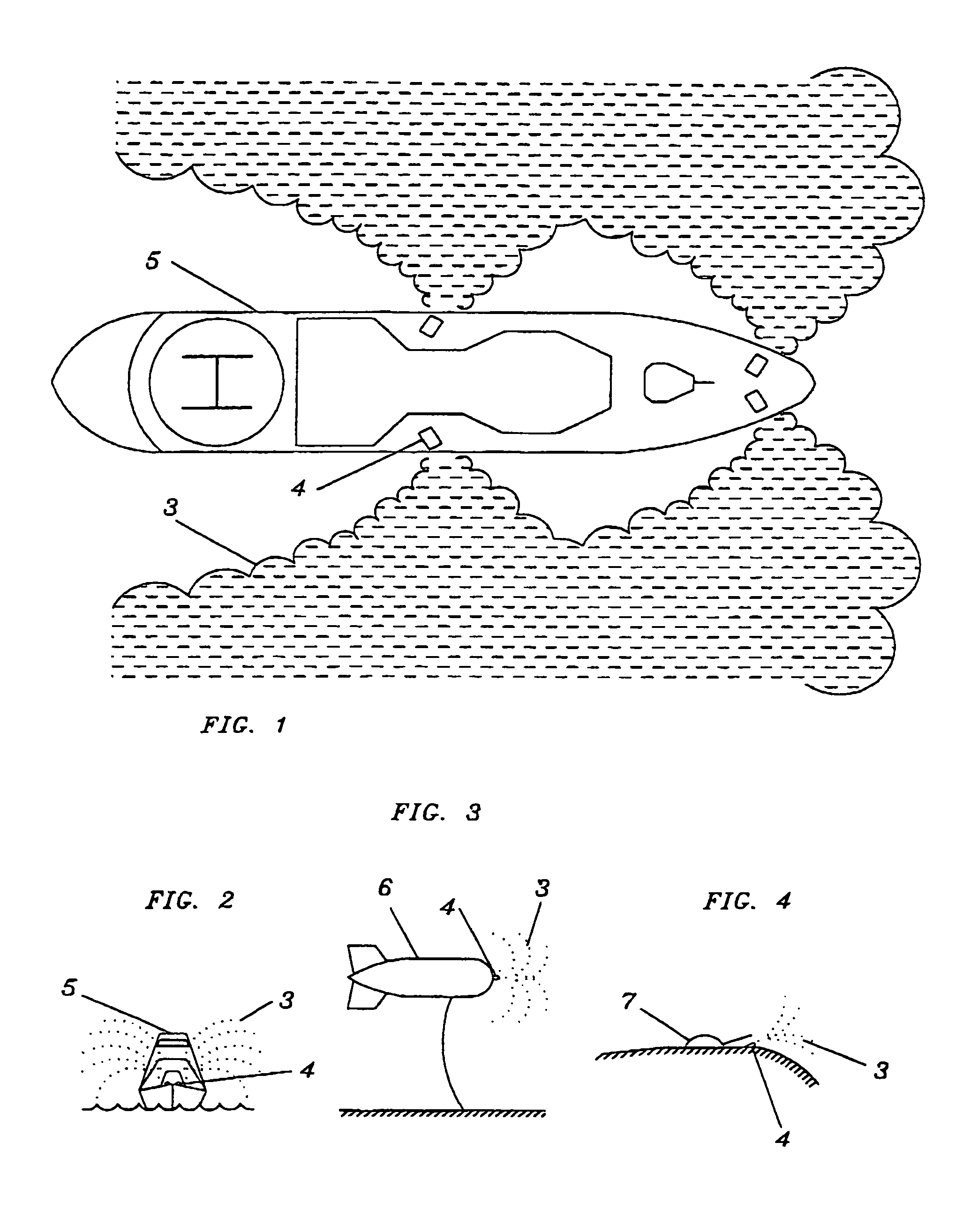
[0020]FIG. 1 shows a ship (5) equipped with a device (4) for generating and spreading mist according to the invention. The device (4) spreads mist (3) round the ship (5). Conveniently the water round the ship is used as liquid to generate the mist (3).

[0021]FIG. 2 shows from the front how a ship (5) equipped with a mist-generating device (4) spreads a mist (3). FIG. 3 shows an air vehicle, in this case an aerostat (6), equipped with a mist-generating device (4). Also helicopters, slow aircraft and ground vehicles...


PUM


Abstract

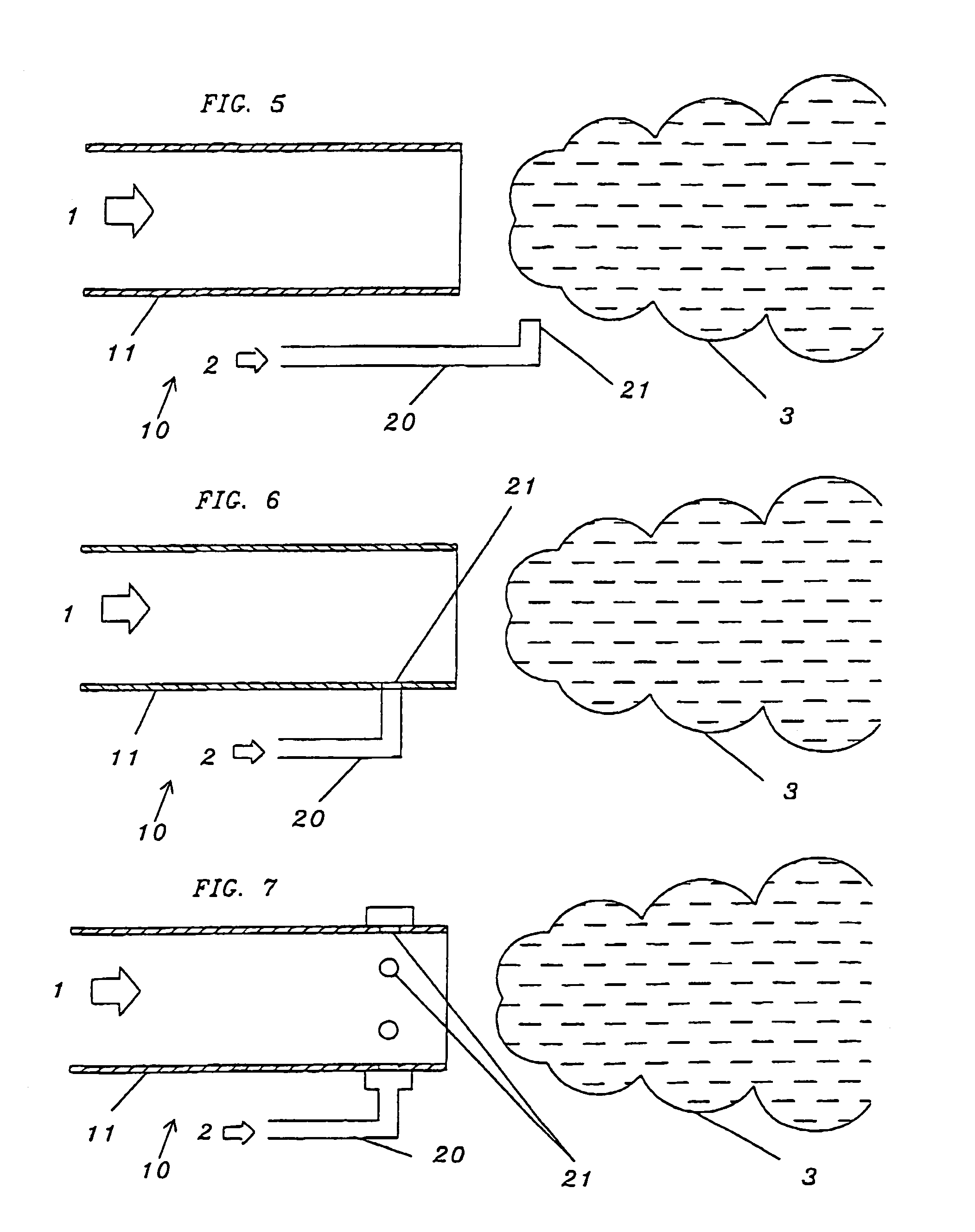
A device and a method for generating a mist for camouflaging ships, vehicles, air vehicles and stationary objects within infrared and radar wavelengths. The device generates mist by a liquid, for instance water, being injected into a flow of air which is supplied from an air duct, through a nozzle directed towards the flow of air. The flow of air atomizes the liquid and spreads the atomized liquid as a mist.

Description

[0001]This is a nationalization of PCT / SE02 / 00581 filed Mar. 22, 2002 and published in English.BACKGROUND OF THE INVENTION[0002]1. Field of the Invention[0003]The present invention relates to a method and a device for generating a liquid mist for camouflage of, inter alia, ships, land vehicles, air vehicles and stationary objects, and as decoy within the infrared and radar wavelengths.[0004]2. Description of the Related Art[0005]It is known that mist, for instance water mist, can be used to camouflage an objector to produce decoys. If an object is covered by water mist, it will be difficult to discover by IR measurement and radar. By controlling temperature and / or size of droplets of the liquid used to generate the mist, it is possible to produce not only camouflage but also a mist which is an effective decoy for radar or IR homing devices.[0006]Known devices for generating mist are using nozzles to atomise the liquid and spread the mist. Liquid under high pressure is used to produc...

Claims


Application Information

Patent Timeline
Patent Type & Authority Patents(United States)
IPC IPC(8): A62C5/02A62C31/00B05B7/04B05B7/08B63G13/02F41H9/06
CPCB63G13/02F41H9/06B63G2013/025
Inventor EKELOF, ANDERS
Owner FORSVARETS MATERIELVERK
Why Eureka
Try Eureka