Novel automatic manipulator

A manipulator and automatic technology, applied in the field of manipulators, can solve the problems of reducing production efficiency, falling of materials, and inaccurate positioning of the lowering position, so as to improve production efficiency and avoid falling.

Inactive Publication Date: 2014-10-08
广东嘉逸实业有限公司
View PDF0 Cites 11 Cited by
  • Summary
  • Abstract
  • Description
  • Claims
  • Application Information

AI Technical Summary

Problems solved by technology

However, due to the inertia of the gripping part when it stops suddenly after moving, the gripping part will continue to move or swing and deform after the sudden stop, which will cause the gripping part to align with the suction position of the material or the lowering position of the material Inaccurate, which will easily lead to the falling of the material and reduce the production efficiency

Method used


Image

  • Novel automatic manipulator
  • Novel automatic manipulator

Examples


Embodiment Construction

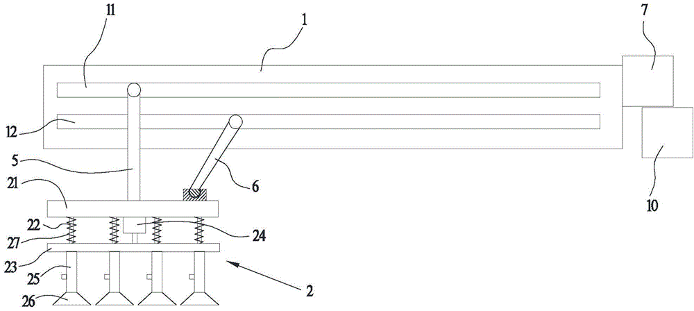
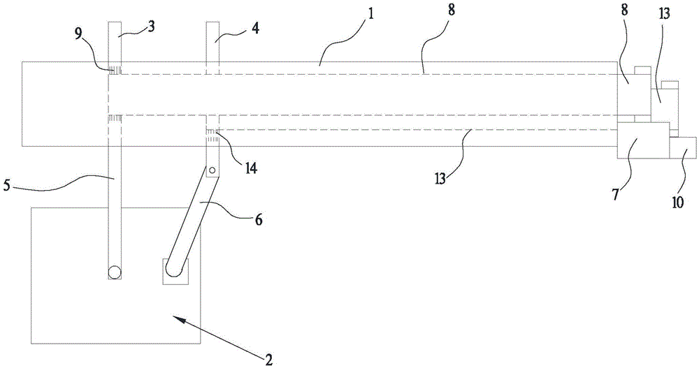
[0015] Such as figure 1 A new type of automatic manipulator is shown, including a guide rail 1, a gripping part 2, a first slide bar 3, a second slide bar 4, a first drive device, a second drive device, a first connecting rod 5 and a second connecting rod 6. The guide rail 1 is provided with a first chute 11 and a second chute 12 along the length direction of the guide rail 1. The first slide bar 3 slides and fits with the first chute 11 and protrudes from the first chute 11. The second slide bar 4 is slidably matched with the second slide slot 12 and protrudes from the second slide slot 12, and the first driving device is drivingly connected with the first slide bar 3 and drives the first slide bar 3 to slide along the first slide slot 11 , the second driving device is drivingly connected with the second slide bar 4 and drives the second slide bar 4 to slide along the second chute 12; the gripping part 2 is connected to the extended end of the first slide bar 3 through the fi...


PUM


Abstract

The invention discloses a novel automatic manipulator which comprises a guide rail, a grabbing portion, a first sliding rod, a second sliding rod, a first driving device, a second driving device, a first connecting rod and a second connecting rod. A first sliding groove and a second sliding groove are formed in the guide rail along the length direction of the same, the first sliding rod is slidably matched with the first sliding groove and extends out from the same, the second sliding rod is slidably matched with the second sliding groove and extends out from the same, the first driving device is in driving connection with the first sliding rod and drives the same to slide along the first sliding groove, and the second driving device is in driving connection with the second sliding rod and drives the second sliding rod to slide along the second sliding groove; the grabbing portion is connected to an extended end of the first sliding rod through the first connecting rod, and one end of the second connecting rod is in ball joint connection with an extended end of the second sliding rod while the other end of the same is in ball joint connection with the grabbing portion. By the novel automatic manipulator, the grabbing portion can be limited, and accurate alignment of materials and parts in the process of sucking-up and putting-down can be realized.

Description

technical field [0001] The invention relates to a manipulator, in particular to a novel automatic manipulator. Background technique [0002] At present, the manipulator used for grabbing injection plastic parts generally hoists the gripping part on the slide rail. The gripping part is generally composed of a suction cup and a telescopic rod. The suction cup moves up and down under the drive of the telescopic rod to suck up the injection molding of materials. However, due to the inertia of the gripping part when it stops suddenly after moving, the gripping part will continue to move or swing and deform after the sudden stop, which will cause the gripping part to align with the suction position of the material or the lowering position of the material Inaccurate, which will easily lead to the drop of the material and reduce the production efficiency. Contents of the invention [0003] In order to overcome the deficiencies of the prior art, the purpose of the present inventi...

Claims


Application Information

Patent Timeline
Patent Type & Authority Applications(China)
IPC IPC(8): B65G47/91
Inventor 杨成祥
Owner 广东嘉逸实业有限公司
Why Eureka
Try Eureka